- 您現(xiàn)在的位置:買賣IC網(wǎng) > PDF目錄384043 > UPD45128441G5-A75-9JF (ELPIDA MEMORY INC) 128M-bit Synchronous DRAM 4-bank, LVTTL PDF資料下載
參數(shù)資料
| 型號(hào): | UPD45128441G5-A75-9JF |
| 廠商: | ELPIDA MEMORY INC |
| 元件分類: | DRAM |
| 英文描述: | 128M-bit Synchronous DRAM 4-bank, LVTTL |
| 中文描述: | 32M X 4 SYNCHRONOUS DRAM, 5.4 ns, PDSO54 |
| 封裝: | PLASTIC, TSOP2-54 |
| 文件頁數(shù): | 35/92頁 |
| 文件大?。?/td> | 682K |
| 代理商: | UPD45128441G5-A75-9JF |
第1頁第2頁第3頁第4頁第5頁第6頁第7頁第8頁第9頁第10頁第11頁第12頁第13頁第14頁第15頁第16頁第17頁第18頁第19頁第20頁第21頁第22頁第23頁第24頁第25頁第26頁第27頁第28頁第29頁第30頁第31頁第32頁第33頁第34頁當(dāng)前第35頁第36頁第37頁第38頁第39頁第40頁第41頁第42頁第43頁第44頁第45頁第46頁第47頁第48頁第49頁第50頁第51頁第52頁第53頁第54頁第55頁第56頁第57頁第58頁第59頁第60頁第61頁第62頁第63頁第64頁第65頁第66頁第67頁第68頁第69頁第70頁第71頁第72頁第73頁第74頁第75頁第76頁第77頁第78頁第79頁第80頁第81頁第82頁第83頁第84頁第85頁第86頁第87頁第88頁第89頁第90頁第91頁第92頁
Data Sheet E0031N30
35
μ
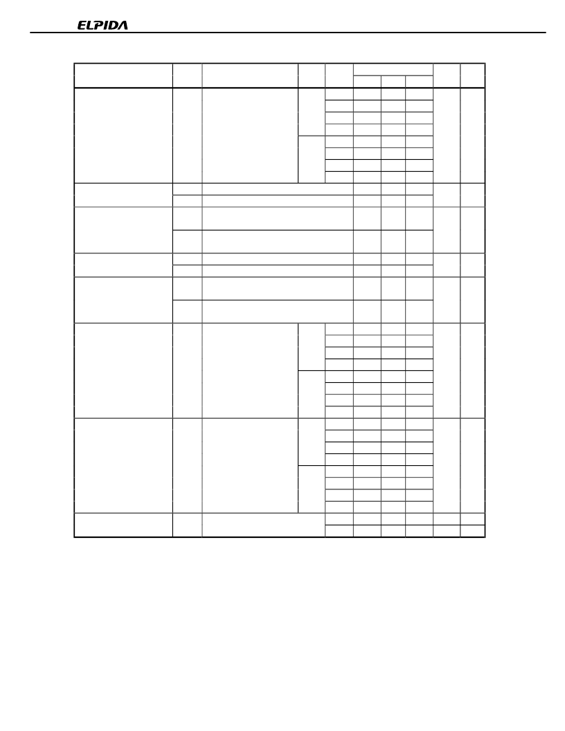
PD45128441, 45128841, 45128163
DC Characteristics 1 (Recommended Operating Conditions unless otherwise noted)
Parameter
Symbol
Test condition
/CAS Grade
Maximum
×
8
Unit
Notes
latency
×
4
×
16
Operating current
I
CC1
Burst length = 1,
t
RC
≥
t
RC (MIN.)
, Io = 0 mA,
One bank active
CL = 2 -A75A
110
110
120
mA
1
-A75
100
100
110
-A80
100
100
110
-A10
100
100
110
CL = 3 -A75A
110
110
120
-A75
105
105
115
-A80
100
100
110
CKE
≤
V
IL (MAX.)
, t
CK
= 15 ns
I
CC2
PS CKE
≤
V
IL (MAX.)
, t
CK
=
∞
I
CC2
N
Input signals are changed one time during 30 ns.
CKE
≥
V
IH (MIN.)
, t
CK
=
∞
,
Input signals are stable.
CKE
≤
V
IL (MAX.)
, t
CK
= 15 ns
I
CC3
PS CKE
≤
V
IL (MAX.)
, t
CK
=
∞
I
CC3
N
Input signals are changed one time during 30 ns.
CKE
≥
V
IH (MIN.)
, t
CK
=
∞
,
Input signals are stable.
t
CK
≥
t
CK (MIN.)
, Io = 0 mA,
All banks active
-A10
100
100
110
Precharge standby current
I
CC2
P
1
1
1
mA
in power down mode
1
1
1
Precharge standby current
in non power down mode
CKE
≥
V
IH (MIN.)
, t
CK
= 15 ns, /CS
≥
V
IH (MIN.)
,
20
20
20
mA
I
CC2
NS
8
8
8
Active standby current
I
CC3
P
5
5
5
mA
in power down mode
4
4
4
Active standby current
in non power down mode
CKE
≥
V
IH (MIN.)
, t
CK
= 15 ns, /CS
≥
V
IH (MIN.)
,
30
30
30
mA
I
CC3
NS
20
20
20
Operating current
I
CC4
CL = 2 -A75A
140
155
185
mA
2
(Burst mode)
-A75
105
120
145
-A80
105
120
145
-A10
85
95
110
CL = 3 -A75A
140
155
185
-A75
140
155
185
-A80
130
145
175
-A10
110
125
140
CBR (auto) refresh current
I
CC5
t
RC
≥
t
RC (MIN.)
CL = 2 -A75A
270
270
270
mA
3
-A75
230
230
230
-A80
230
230
230
-A10
230
230
230
CL = 3 -A75A
270
270
270
-A75
240
240
240
-A80
230
230
230
CKE
≤
0.2 V
-A10
230
230
230
Self refresh current
I
CC6
-**
2
2
2
mA
-**L
0.8
0.8
0.8
mA
Notes 1.
I
CC1
depends on output loading and cycle rates. Specified values are obtained with the output open. In
addition to this, I
CC1
is measured condition that addresses are changed only one time during t
CK (MIN.)
.
2.
I
CC4
depends on output loading and cycle rates. Specified values are obtained with the output open. In
addition to this, I
CC4
is measured condition that addresses are changed only one time during t
CK (MIN.)
.
3.
I
CC5
is measured on condition that addresses are changed only one time during t
CK (MIN.)
.
相關(guān)PDF資料 |
PDF描述 |
|---|---|
| UPD45128841G5-A75L-9JF | 128M-bit Synchronous DRAM 4-bank, LVTTL |
| UPD45128841G5-A80-9JF | 128M-bit Synchronous DRAM 4-bank, LVTTL |
| UPD45128841G5-A80L-9JF | 128M-bit Synchronous DRAM 4-bank, LVTTL |
| UPD45128441G5-A75L-9JF | 128M-bit Synchronous DRAM 4-bank, LVTTL |
| UPD45128163G5-A75-9JF | 128M-bit Synchronous DRAM 4-bank, LVTTL |
相關(guān)代理商/技術(shù)參數(shù) |
參數(shù)描述 |
|---|---|
| UPD45128841G5-A75-9JF | 制造商:NEC Electronics Corporation 功能描述:SDRAM, 16M x 8, 54 Pin, Plastic, TSOP |
| UPD4516161AG5A109NF | 制造商:NEC Electronics Corporation 功能描述: |
| UPD4516161AG5-A10-9NF | 制造商:NEC Electronics Corporation 功能描述:SDRAM, 1M x 16, 50 Pin, Plastic, TSOP |
| UPD4528BC | 制造商:Panasonic Industrial Company 功能描述:IC |
| UPD4528C | 制造商:Panasonic Industrial Company 功能描述:IC SUB:TC4528BP OR TVSTC4528BP |
發(fā)布緊急采購,3分鐘左右您將得到回復(fù)。