- 您現(xiàn)在的位置:買賣IC網(wǎng) > PDF目錄376431 > UPD75066GB (NEC Corp.) 4-BIT SINGLE-CHIP MICROCOMPUTER PDF資料下載
參數(shù)資料
| 型號: | UPD75066GB |
| 廠商: | NEC Corp. |
| 英文描述: | 4-BIT SINGLE-CHIP MICROCOMPUTER |
| 中文描述: | 4位單片機(jī) |
| 文件頁數(shù): | 27/68頁 |
| 文件大小: | 640K |
| 代理商: | UPD75066GB |
第1頁第2頁第3頁第4頁第5頁第6頁第7頁第8頁第9頁第10頁第11頁第12頁第13頁第14頁第15頁第16頁第17頁第18頁第19頁第20頁第21頁第22頁第23頁第24頁第25頁第26頁當(dāng)前第27頁第28頁第29頁第30頁第31頁第32頁第33頁第34頁第35頁第36頁第37頁第38頁第39頁第40頁第41頁第42頁第43頁第44頁第45頁第46頁第47頁第48頁第49頁第50頁第51頁第52頁第53頁第54頁第55頁第56頁第57頁第58頁第59頁第60頁第61頁第62頁第63頁第64頁第65頁第66頁第67頁第68頁

27
μ
PD75064, 75066, 75068, 75064(A), 75066(A), 75068(A)
6. INTERRUPT FUNCTIONS
The
μ
PD75068 has six different interrupt sources. In addition, multiple interrupts with priority control are
possible. Two types of test sources are provided. Of these test sources, INT2 has two types of edge detection
testable inputs.
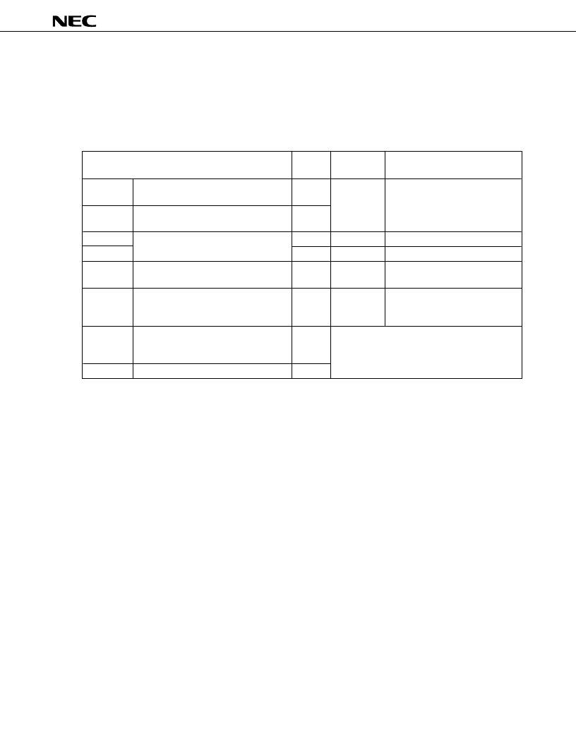
Table 6-1. Interruption Source Types
Interruption
Order
Note1
Vectored Interrupt Request Signal
(Vector table address)
Interruption Source
IN/OUT
(Reference time interval signal from
basic interval timer)
(Detection of both rising edge and
falling edge is valid.)
OUT
2
VRQ2 (0004H)
OUT
3
VRQ3 (0006H)
(Serial data transmission completion
signal)
(Coincidence signal of programmable
timer/counter count register and modulo
register)
INTT0
IN
5
VRQ5 (000AH)
(Detection of rising edge of input to
INT2 pin or detection of falling edge of
any input to KR0 to KR3)
INT2
Note2
OUT
INTW
Note2
(Signal from watch timer)
IN
Notes 1.
The interruption order shows the priority order of the pins when several interruption requests occur
at the same time.
2.
Test source. Like the interruption source, it is influenced by the interruption enable flag. However,
vectored interrupt will not occur.
The interrupt control circuit of the
μ
PD75068 has the following functions:
Hardware controlled vectored interrupt function which can control whether or not to acknowledge an
interrupt based on the interrupt flag (IE
×××
) and interrupt master enable flag (IME)
The interrupt start address can be set arbitrarily.
Interrupt request flag (IRQ
×××
) test function (an interrupt generation can be confirmed by software)
Standby mode release (interrupts to be released can be selected by the interrupt enable flag)
IN
INTBT
INT4
(Selection of rising edge detection or
falling edge detection)
INT0
INT1
INTCSI
VRQ1 (0002H)
1
Test input signal (Set IRQ and IRQW)
VRQ4 (0008H)
4
IN
OUT
相關(guān)PDF資料 |
PDF描述 |
|---|---|
| UPD75066GBA | 4-BIT SINGLE-CHIP MICROCOMPUTER |
| UPD75068 | 4-BIT SINGLE-CHIP MICROCOMPUTER |
| UPD75068A | 4-BIT SINGLE-CHIP MICROCOMPUTER |
| UPD75068CU | 4-BIT SINGLE-CHIP MICROCOMPUTER |
| UPD75068GB | 4-BIT SINGLE-CHIP MICROCOMPUTER |
相關(guān)代理商/技術(shù)參數(shù) |
參數(shù)描述 |
|---|---|
| UPD7507C189 | 制造商:Panasonic Industrial Company 功能描述:IC |
| UPD7508CU265 | 制造商:Panasonic Industrial Company 功能描述:IC |
| UPD75208 | 制造商:Panasonic Industrial Company 功能描述:IC |
| UPD753012AGC-P33-8BT-A | 制造商:Renesas Electronics Corporation 功能描述: |
| UPD753016AGC-P29-8BT | 制造商:Renesas Electronics Corporation 功能描述: |
發(fā)布緊急采購,3分鐘左右您將得到回復(fù)。