- 您現(xiàn)在的位置:買賣IC網(wǎng) > PDF目錄376431 > UPD75112CWA (NEC Corp.) 4-Bit Single Chip-Microcomputer PDF資料下載
參數(shù)資料
| 型號(hào): | UPD75112CWA |
| 廠商: | NEC Corp. |
| 英文描述: | 4-Bit Single Chip-Microcomputer |
| 中文描述: | 4位單片微機(jī) |
| 文件頁數(shù): | 11/56頁 |
| 文件大小: | 499K |
| 代理商: | UPD75112CWA |
第1頁第2頁第3頁第4頁第5頁第6頁第7頁第8頁第9頁第10頁當(dāng)前第11頁第12頁第13頁第14頁第15頁第16頁第17頁第18頁第19頁第20頁第21頁第22頁第23頁第24頁第25頁第26頁第27頁第28頁第29頁第30頁第31頁第32頁第33頁第34頁第35頁第36頁第37頁第38頁第39頁第40頁第41頁第42頁第43頁第44頁第45頁第46頁第47頁第48頁第49頁第50頁第51頁第52頁第53頁第54頁第55頁第56頁

11
μ
PD75112(A), 75116(A)
4. Memory Configuration
Program Memory (ROM)
12160
×
8 bits (0000H to 2F7FH):
μ
PD75112(A)
16256
×
8 bits (0000H to 3F7FH):
μ
PD75116(A)
0000H to 0001H: Vector table for writing the
program start address by reset
0002H to 000BH: Vector table for writing the
program start address by interrupt
Remarks
: In all other cases, the program can be
branched by the BR PCDE and BR PCXA
0020H to 007FH: Table area to be referred to
by the GETI instruction
Data Memory
Data area
512
×
4 bits (000H to 1FFH)
Peripheral hardware area
128
×
4 bits (F80H to FFFH)
instructions to an address with only the
lower 8 bits of PC changed.
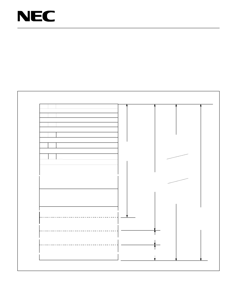
Figure 4-1 Program Memory Map (
μ
PD75112(A))
Address
≈
≈
≈
MBE RBE
MBE RBE
MBE
MBE RBE
MBE RBE
MBE RBE
0000H
0002H
0004H
0006H
0008H
000AH
0020H
007FH
0080H
07FFH
0800H
0FFFH
1000H
7
6
0
Internal Reset Start Address
Internal Reset Start Address (Low-Order 8 Bits)
INTBT/INT4 Start Address (High-Order 6 Bits)
INT0/INT1 Start Address (High-Order 6 Bits)
RBE
INT0/INT1 Start Address
(Low-Order 8 Bits)
(Low-Order 8 Bits)
INTSIO Start Address (High-Order 6 Bits)
INTSIO Start Address
(Low-Order 8 Bits)
INTT0 Start Address (High-Order 6 Bits)
INTT0 Start Address
(Low-Order 8 Bits)
INTT1 Start Address (High-Order 6 Bits)
INTT1 Start Address
GETI Instruction Reference Table
CALLF
! faddr
Instruction
Entry
Address
BRCB
! caddr
Instruction
Branch
Address
BR !addr
Instruction
Branch
Address
CALL !addr
Instruction
Subroutin
Entry
Address
BRCB !caddr Instruction
Branch Address
≈
(High-Order 6 Bits)
INTBT/INT4 Start Address
(Low-Order 8 Bits)
≈
≈
≈
≈
≈
≈
2000H
1FFFH
2F7FH
BRCB !caddr Instruction
Branch Address
BR $addr
Instruction
Relative
Branch Address
(-15 to +16)
Branch Address
Subroutine Entry
Address by GETI
Instruction
相關(guān)PDF資料 |
PDF描述 |
|---|---|
| UPD75112 | 4-Bit Single Chip-Microcomputer |
| UPD75112A | 4-Bit Single Chip-Microcomputer |
| UPD75112CW | 4-Bit Single Chip-Microcomputer |
| UPD75112GF | 4-Bit Single Chip-Microcomputer |
| UPD75112GFA | 4-Bit Single Chip-Microcomputer |
相關(guān)代理商/技術(shù)參數(shù) |
參數(shù)描述 |
|---|---|
| UPD75208 | 制造商:Panasonic Industrial Company 功能描述:IC |
| UPD753012AGC-P33-8BT-A | 制造商:Renesas Electronics Corporation 功能描述: |
| UPD753016AGC-P29-8BT | 制造商:Renesas Electronics Corporation 功能描述: |
| UPD75304GF-407-3B9 | 制造商:Renesas Electronics Corporation 功能描述: |
| UPD75306G182 | 制造商:Panasonic Industrial Company 功能描述:IC |
發(fā)布緊急采購,3分鐘左右您將得到回復(fù)。