- 您現(xiàn)在的位置:買賣IC網(wǎng) > PDF目錄376431 > UPD75208 (NEC Corp.) 4-BIT SINGLE-CHIP MICROCOMPUTER PDF資料下載
參數(shù)資料
| 型號: | UPD75208 |
| 廠商: | NEC Corp. |
| 英文描述: | 4-BIT SINGLE-CHIP MICROCOMPUTER |
| 中文描述: | 4位單片機(jī) |
| 文件頁數(shù): | 12/62頁 |
| 文件大小: | 497K |
| 代理商: | UPD75208 |
第1頁第2頁第3頁第4頁第5頁第6頁第7頁第8頁第9頁第10頁第11頁當(dāng)前第12頁第13頁第14頁第15頁第16頁第17頁第18頁第19頁第20頁第21頁第22頁第23頁第24頁第25頁第26頁第27頁第28頁第29頁第30頁第31頁第32頁第33頁第34頁第35頁第36頁第37頁第38頁第39頁第40頁第41頁第42頁第43頁第44頁第45頁第46頁第47頁第48頁第49頁第50頁第51頁第52頁第53頁第54頁第55頁第56頁第57頁第58頁第59頁第60頁第61頁第62頁

12
μ
PD75208
4.
ARCHITECTURE AND MEMORY MAP OF THE
μ
PD75208
The
μ
PD75208 has three architectural features:
Bank configuration of data memory
: Static RAM (448 words
×
4 bits)
Display data memory (49 words
×
4 bits)
Peripheral hardware (128
×
4 bits)
Bank configuration of general registers: 8
×
4 banks (for operation in 4-bit units)
4
×
4 banks (for operation in 8-bit units)
Memory mapped I/O
Fig. 4-1 and 4-2 show the memory maps for the
μ
PD75208.
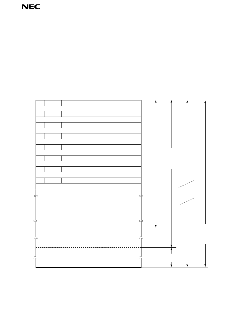
Fig. 4-1 Program Memory Map
Remarks
In all cases other than those listed above, branch to the address with only the lower 8 bits of the PC
changed is enabled by BR PCDE and BR PCXA instructions.
MBE RBE
0
7
6
5
0000H
Address
MBE RBE
0
0002H
MBE RBE
0
0004H
MBE RBE
0
0006H
MBE RBE
0
0008H
MBE RBE
0
000AH
007FH
0080H
0020H
1F7FH
0
Internal Reset Start Address High-Order 5 Bits)
Internal Reset Start Address (Low-Order 8 Bits)
INTBT/INT4 Start Address (High-Order 5 Bits)
INTBT/INT4 Start Address (Low-Order 8 Bits)
INT0 Start Address (High-Order 5 Bits)
INT0 Start Address (Low-Order 8 Bits)
INT1 Start Address (High-Order 5 Bits)
INT1 Start Address (Low-Order 8 Bits)
INTSIO Start Address (High-Order 5 Bits)
INTSIO Start Address (Low-Order 8 Bits)
INTT0 Start Address (High-Order 5 Bits)
INTT0 Start Address (Low-Order 8 Bits)
NTTPG Start Address (High-Order 5 Bits)
INTTPG Start Address (Low-Order 8 Bits)
INTKS Start Address
(High-Order 5 Bits)
INTKS Start Address
(Low-Order 8 Bits)
GETI Instruction Reference Table
000EH
MBE RBE
0
MBE RBE
0
000CH
07FFH
0800H
0FFFH
1000H
BRCB
! caddr Instruction
Branch Address
CALL ! addr
Instruction
Subroutine Entry
Address
BR ! addr
Instruction Branch
Address
BR $addr
Instruction
Relative Branch
Address
(–15 to –1,
+2 to +16)
BRCB
! caddr
Instruction
Branch
Address
CALLF
! faddr
Instruction
Entry
Address
Branch Destination
Address Specified
by GETI Instruction,
Subroutine Entry
Address
相關(guān)PDF資料 |
PDF描述 |
|---|---|
| UPD75208CW | 4-BIT SINGLE-CHIP MICROCOMPUTER |
| UPD753208GT | 4-BIT SINGLE-CHIP MICROCONTROLLERS |
| UPD753204 | 4-BIT SINGLE-CHIP MICROCONTROLLERS |
| UPD753204GT | 4-BIT SINGLE-CHIP MICROCONTROLLERS |
| UPD753208 | 4-BIT SINGLE-CHIP MICROCONTROLLERS |
相關(guān)代理商/技術(shù)參數(shù) |
參數(shù)描述 |
|---|---|
| UPD753012AGC-P33-8BT-A | 制造商:Renesas Electronics Corporation 功能描述: |
| UPD753016AGC-P29-8BT | 制造商:Renesas Electronics Corporation 功能描述: |
| UPD75304GF-407-3B9 | 制造商:Renesas Electronics Corporation 功能描述: |
| UPD75306G182 | 制造商:Panasonic Industrial Company 功能描述:IC |
| UPD75308F478 | 制造商:Panasonic Industrial Company 功能描述:IC |
發(fā)布緊急采購,3分鐘左右您將得到回復(fù)。