- 您現(xiàn)在的位置:買賣IC網(wǎng) > PDF目錄378747 > UPD75316BGK (NEC Corp.) 4-BIT SINGLE-CHIP MICROCOMPUTER PDF資料下載
參數(shù)資料
| 型號(hào): | UPD75316BGK |
| 廠商: | NEC Corp. |
| 英文描述: | 4-BIT SINGLE-CHIP MICROCOMPUTER |
| 中文描述: | 4位單片機(jī) |
| 文件頁(yè)數(shù): | 71/77頁(yè) |
| 文件大小: | 587K |
| 代理商: | UPD75316BGK |
第1頁(yè)第2頁(yè)第3頁(yè)第4頁(yè)第5頁(yè)第6頁(yè)第7頁(yè)第8頁(yè)第9頁(yè)第10頁(yè)第11頁(yè)第12頁(yè)第13頁(yè)第14頁(yè)第15頁(yè)第16頁(yè)第17頁(yè)第18頁(yè)第19頁(yè)第20頁(yè)第21頁(yè)第22頁(yè)第23頁(yè)第24頁(yè)第25頁(yè)第26頁(yè)第27頁(yè)第28頁(yè)第29頁(yè)第30頁(yè)第31頁(yè)第32頁(yè)第33頁(yè)第34頁(yè)第35頁(yè)第36頁(yè)第37頁(yè)第38頁(yè)第39頁(yè)第40頁(yè)第41頁(yè)第42頁(yè)第43頁(yè)第44頁(yè)第45頁(yè)第46頁(yè)第47頁(yè)第48頁(yè)第49頁(yè)第50頁(yè)第51頁(yè)第52頁(yè)第53頁(yè)第54頁(yè)第55頁(yè)第56頁(yè)第57頁(yè)第58頁(yè)第59頁(yè)第60頁(yè)第61頁(yè)第62頁(yè)第63頁(yè)第64頁(yè)第65頁(yè)第66頁(yè)第67頁(yè)第68頁(yè)第69頁(yè)第70頁(yè)當(dāng)前第71頁(yè)第72頁(yè)第73頁(yè)第74頁(yè)第75頁(yè)第76頁(yè)第77頁(yè)
71
μ
PD75312B, 75316B
14. RECOMMENDED SOLDERING CONDITIONS
The product
should be soldered and mounted under the conditions recommended in the table below.
For the details of recommended soldering conditions, refer to the information document “
Semiconductor Device
Mounting Technology Manual
” (IEI-1207).
For soldering methods and conditions other than those recommended below, contact an NEC sales represen-
tative.
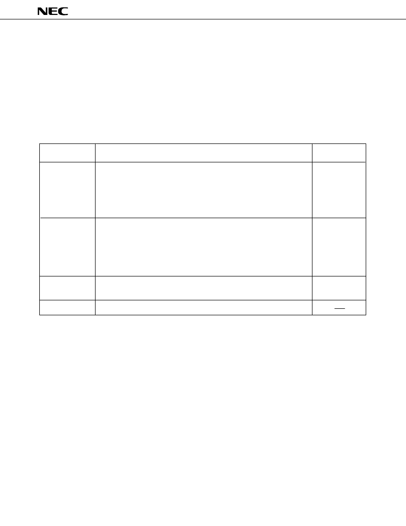
Table 14-1 Surface Mounting Type Soldering Conditions
μ
PD75312BGC-
×××
-3B9
: 80-pin plastic QFP (14 x 14 mm)
μ
PD75316BGC-
×××
-3B9
: 80-pin plastic QFP (14 x 14 mm)
Recommended
Condition Symbol
Package peak temperature: 235
°
C, Time: Within 30 s (at 210
°
C or higher), Count:
Twice or less
<Attention>
(1)
Perform the second reflow when the device temperature has come down to
the room temperature from the heating by the first reflow.
Do not wash flux away with water after the first reflow.
(2)
Package peak temperature: 215
°
C, Time: Within 40 s (at 200
°
C or higher), Count:
Twice or less
<Attention>
(1)
Perform the second reflow when the device temperature has come down to
the room temperature from the heating by the first reflow.
Do not wash flux away with water after the first reflow.
(2)
Soldering tank temperature: 260
°
C or less, Time: Within 10 s, Count: Once,
Preheating temperature: 120
°
C MAX. (package surface temperature)
Pin temperature: 300
°
C or less, Time: Within 3 s (per side of device)
IR35-00-2
VP15-00-2
WS60-00-1
Partial heating
Infrared reflow
VPS
Wave soldering
Caution:
Do not use several soldering methods in combination (except partial heating).
Soldering Method
Soldering Conditions
相關(guān)PDF資料 |
PDF描述 |
|---|---|
| UPD75312 | 4-BIT SINGLE-CHIP MICROCOMPUTER |
| UPD75316GFA | 4-BIT SINGLE-CHIP MICROCOMPUTER |
| UPD75312GF | 4-BIT SINGLE-CHIP MICROCOMPUTER |
| UPD75312GFA | 4-BIT SINGLE-CHIP MICROCOMPUTER |
| UPD75312A | 4-BIT SINGLE-CHIP MICROCOMPUTER |
相關(guān)代理商/技術(shù)參數(shù) |
參數(shù)描述 |
|---|---|
| UPD753204013 | 制造商:Panasonic Industrial Company 功能描述:IC |
| UPD7554AG-597-E2 | 制造商:Renesas Electronics Corporation 功能描述: |
| UPD7554AG-597-E2-A | 制造商:Renesas Electronics Corporation 功能描述: |
| UPD7554AG-603-E2 | 制造商:Renesas Electronics Corporation 功能描述: |
| UPD7554AG-603-E2-A | 制造商:Renesas Electronics Corporation 功能描述: |
發(fā)布緊急采購(gòu),3分鐘左右您將得到回復(fù)。