- 您現(xiàn)在的位置:買賣IC網(wǎng) > PDF目錄361619 > V23818K305V10 FIBER OPTIC TRANSCEIVER PDF資料下載
參數(shù)資料
| 型號: | V23818K305V10 |
| 英文描述: | FIBER OPTIC TRANSCEIVER |
| 中文描述: | 光纖收發(fā)器 |
| 文件頁數(shù): | 2/14頁 |
| 文件大?。?/td> | 1007K |
| 代理商: | V23818K305V10 |
Fiber Optics
V23814/15-K1306-M230 Parallel Optical Link: PAROLI Tx/Rx DC
2
DESCRIPTION
PAROLI is a parallel optical link for high-speed data transmis-
sion. A complete PAROLI system consists of a transmitter
module, a 12-channel fiber optic cable, and a receiver module.
Transmitter V23814-K1306-M230
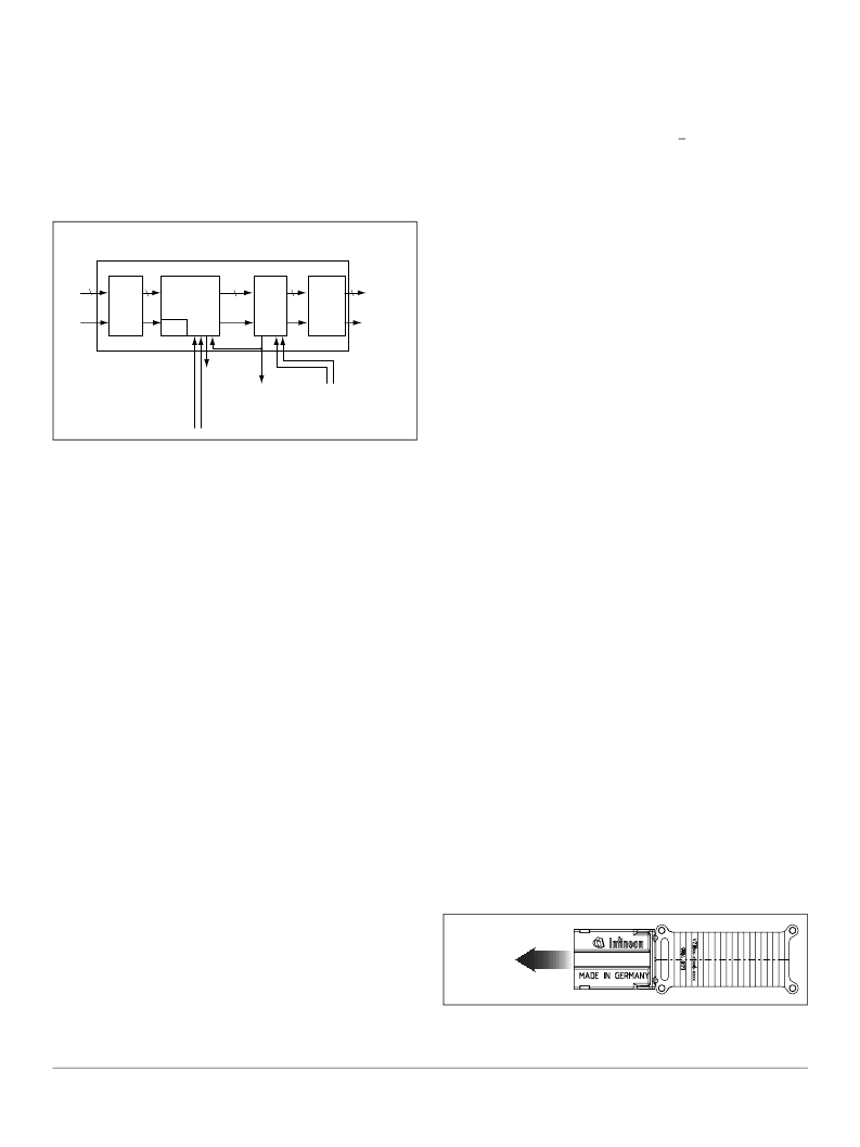
The PAROLI transmitter module converts parallel electrical
input signals (data and clock) into parallel optical output signals.
Figure 1. Transmitter block diagram
All electrical data and clock inputs are LVDS compatible. The
module also features several LVCMOS compatible control
inputs and outputs, which are described in the Transmitter Pin
Description (table starting on page 5).
The module features multiplexing and encoding of 22 electrical
data input channels to 11 optical data output channels. The
input data are serialized by 2 to 1 multiplexers which results in a
reduced data rate at the electrical interface. The multiplexed
data are encoded (4B/5B encoding) to achieve DC-balanced sig-
nals at the input of the laser driver.
The electrical input clock signal is used to control an integrated
PLL circuit, which generates internal clock signals for encoding
and multiplexing. The PLL circuit also generates a frame signal
for the optical interface, which is transmitted over a separate
fiber.
Transmission delay of the PAROLI system is at a maximum of
4 strobe cycles + 3 ns for the transmitter, 3 strobe cycles + 3 ns
for the receiver, and approximately 5 ns per meter for the fiber
optic cable.
Clocking Modes
The transmitter can be operated in one of two input clocking
modes: Strobe mode or SCI mode. The mode is selected via
CLK_SEL input. In Strobe mode, the rising edges of the non-
inverted clock signal are centered over the data bits. In SCI
mode, High/Low transitions of clock and data signals coincide.
In SCI mode, the transmitter‘s electrical interface complies with
the SCI standard. See Timing diagram Figure 5 on page 4.
Multiplexing and Encoding
The electrical input data are strobed into the input register with
the internal clock signal generated by the PLL and then multi-
plexed 2:1. Input channels 1 to 11 are grouped with input chan-
nels 12 to 22, i.e. data inputs 1 and 12 feed optical data output
1; data inputs 2 and 13 feed optical data output 2, etc.
Four data bits read from two input channels during two strobe
cycles form 4B words. Inside the 4B word, data from the lower
inputs (1 to 11) is transmitted first, i.e. after input data are
strobed. Inputs 1 to 11 are routed before inputs 12 to 22. 4B
words are then fed through eleven separate 4B/5B encoders to
form the signals to be transmitted over the optical interface.
Coding is based on the running disparity of previously transmit-
ted output data. With a running disparity
=
>
0, either more High
than Low levels or an equal number of Highs and Lows have
been transmitted. The next output nibble will be inverted if High
levels again dominate; otherwise it will be sent without inver-
sion. With a running disparity <0, more Low than High levels
have been transmitted. The next output nibble will be inverted if
Low levels again dominate; otherwise it will be sent uninverted.
To indicate whether a nibble has been inverted, an inversion bit
is added, thus forming a 5B word (High, if transmitted nibble is
uninverted; Low, if transmitted nibble is inverted). It is placed in
front of the nibble (at the beginning of the 5B word) and imme-
diately follows the FRAME transition. FRAME signal transitions
delimit 5B words. Each 5B word contains the inversion bit and
the nibble (inverted or non-inverted) mounted from two input
data strobe cycles. The 5B words and FRAME signal are the
signals transmitted over the optical interface. The pulse lengths
of the 5B word and the frame signal is twice the pulse length of
the electrical input signal.
Example
To transmit electrical data at the maximum data rate of 500
Mbit/s per channel the corresponding clock signal (square 0101
pattern) has a frequency of 250 MHz in SCI mode or 500 MHz
in STROBE mode. The FRAME signal with a corresponding fre-
quency of 125 MHz is transmitted via fiber #1. The data rate of
the optical signal at the Transmitter output is 1.25 Gbit/s in each
of the fibers #2 to #12.
LASER SAFETY
The transmitter of the DC coupled Parallel Optical Link (PAROLI)
is an FDA Class 1 laser product. It complies with FDA regula-
tions 21 CFR 1040.10 and 1040.11. The transmitter is an IEC
Class 3A laser product as defined by IEC 60825-1. To avoid pos-
sible exposure to hazardous levels of invisible radiation, do not
exceed maximum ratings.
The PAROLI module must be operated under the specified
operating conditions (supply voltage between 3.0 V and 3.6 V,
case temperature between 0°C and 80°C) under all circum-
stances to ensure laser safety.
Caution
Do not stare into beam or view directly with optical
instruments. The use of optical instruments with this product
will increase eye hazard.
Note
Any modification of the module will be considered an act of “manu-
facturing,” and will require, under law, recertification of the product
under FDA (21 CFR 1040.10 (i)).
Figure 2. Laser emission
PLL
-RESET
CLK_SEL
Laser
Controller Up
Module
Up
Data
Fibers
Frame
Fiber #1
Clock
Input
Data
Inputs
Electrical
Inputs
Optical
Outputs
LE
Laser Enable
-LE
Input
Stage
Multiplexer
Encoder
Laser
Driver
VCSEL
Array
22
22
11
11
11
Frame
Laser aperture
and beam
相關PDF資料 |
PDF描述 |
|---|---|
| V23818-M305-L58 | Telecomm/Datacomm |
| V23826H18C13 | FIBER OPTIC TRANSCEIVER |
| V23826H18C16 | FIBER OPTIC TRANSCEIVER |
| V23826H18C313 | FIBER OPTIC TRANSCEIVER |
| V23826H18C316 | FIBER OPTIC TRANSCEIVER |
相關代理商/技術參數(shù) |
參數(shù)描述 |
|---|---|
| V23818-M305-B57 | 功能描述:TXRX ETHRNET MULT-MODE 1.25GBIT RoHS:否 類別:光電元件 >> 光纖 - 收發(fā)器 系列:- 標準包裝:20 系列:* |
| V23818-M305-L57 | 功能描述:TXRX ETHRNET MULT-MODE 1.25GBIT RoHS:否 類別:光電元件 >> 光纖 - 收發(fā)器 系列:- 標準包裝:20 系列:* |
| V23818-M305-L58 | 制造商:未知廠家 制造商全稱:未知廠家 功能描述:Telecomm/Datacomm |
| V23818-N15-L16 | 制造商:INFINEON 制造商全稱:Infineon Technologies AG 功能描述:Small Form Factor Single Mode 1300 nm Multirate up to 2.5 Gbit/s Transceiver 2x5/2x10 Pinning with LCa?¢ Connector |
| V23818-N15-L17 | 制造商:INFINEON 制造商全稱:Infineon Technologies AG 功能描述:Small Form Factor Single Mode 1300 nm Multirate up to 2.5 Gbit/s Transceiver 2x5/2x10 Pinning with LCa?¢ Connector |
發(fā)布緊急采購,3分鐘左右您將得到回復。