- 您現(xiàn)在的位置:買賣IC網(wǎng) > PDF目錄361790 > W741C250 4-Bit Microcontroller PDF資料下載
參數(shù)資料
| 型號(hào): | W741C250 |
| 英文描述: | 4-Bit Microcontroller |
| 中文描述: | 4位微控制器 |
| 文件頁(yè)數(shù): | 16/88頁(yè) |
| 文件大小: | 449K |
| 代理商: | W741C250 |
第1頁(yè)第2頁(yè)第3頁(yè)第4頁(yè)第5頁(yè)第6頁(yè)第7頁(yè)第8頁(yè)第9頁(yè)第10頁(yè)第11頁(yè)第12頁(yè)第13頁(yè)第14頁(yè)第15頁(yè)當(dāng)前第16頁(yè)第17頁(yè)第18頁(yè)第19頁(yè)第20頁(yè)第21頁(yè)第22頁(yè)第23頁(yè)第24頁(yè)第25頁(yè)第26頁(yè)第27頁(yè)第28頁(yè)第29頁(yè)第30頁(yè)第31頁(yè)第32頁(yè)第33頁(yè)第34頁(yè)第35頁(yè)第36頁(yè)第37頁(yè)第38頁(yè)第39頁(yè)第40頁(yè)第41頁(yè)第42頁(yè)第43頁(yè)第44頁(yè)第45頁(yè)第46頁(yè)第47頁(yè)第48頁(yè)第49頁(yè)第50頁(yè)第51頁(yè)第52頁(yè)第53頁(yè)第54頁(yè)第55頁(yè)第56頁(yè)第57頁(yè)第58頁(yè)第59頁(yè)第60頁(yè)第61頁(yè)第62頁(yè)第63頁(yè)第64頁(yè)第65頁(yè)第66頁(yè)第67頁(yè)第68頁(yè)第69頁(yè)第70頁(yè)第71頁(yè)第72頁(yè)第73頁(yè)第74頁(yè)第75頁(yè)第76頁(yè)第77頁(yè)第78頁(yè)第79頁(yè)第80頁(yè)第81頁(yè)第82頁(yè)第83頁(yè)第84頁(yè)第85頁(yè)第86頁(yè)第87頁(yè)第88頁(yè)
W741C250
- 16 -
0
1
2
SEF
w
w
w
w
3
Note: W means write only.
SEF 0 = 1 Device will exit stop mode when falling edge signal is applied to pin RC.0.
SEF 1 = 1 Device will exit stop mode when falling edge signal is applied to pin RC.1.
SEF 2 = 1 Device will exit stop mode when falling edge signal is applied to pin RC.2.
SEF 3 = 1 Device will exit stop mode when falling edge signal is applied to pin RC.3.
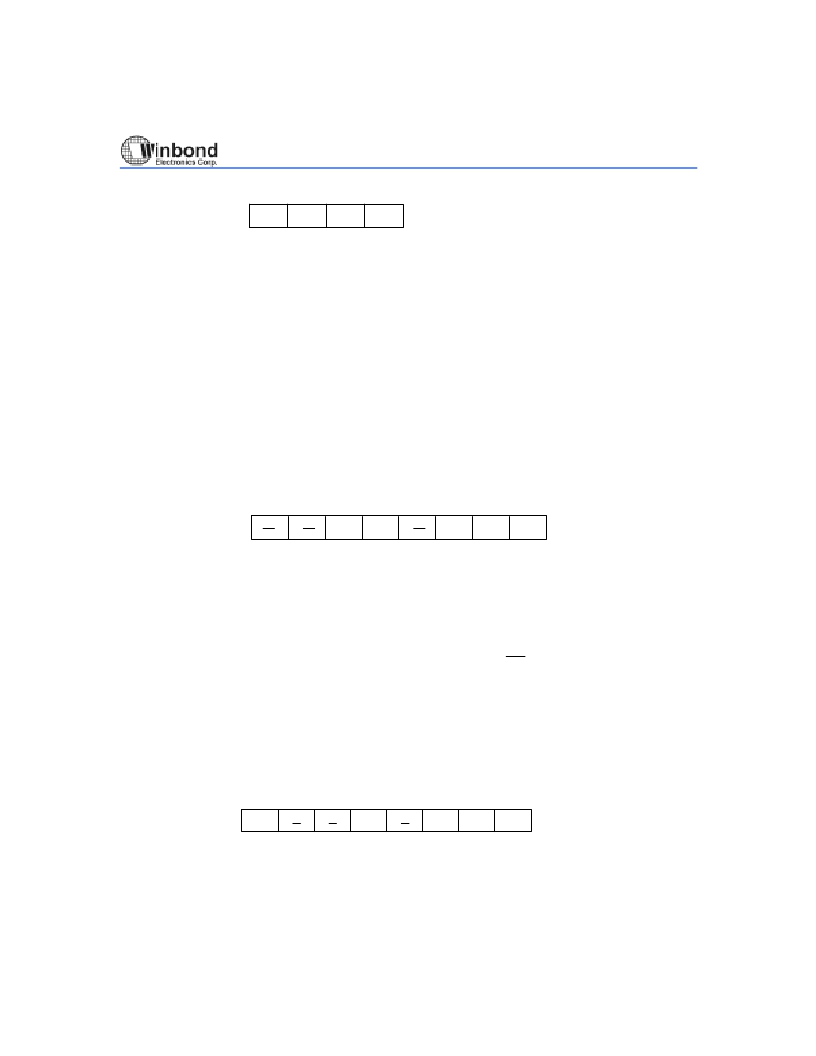
Hold Mode Release Condition Flag (HCF)
The hold mode release condition flag is organized as an 8-bit binary register (HCF0 to HCF7). It
indicates by which interrupt source the hold mode has been released, and it is loaded by hardware.
The HCF can be read out by the MOVA R, HCFL
and MOVA R, HCFH instructions. When any of the
HCF bits is "1," the hold mode will be released and the HOLD instruction is invalid. The HCF can be
reset by the CLR EVF, #I (EVF.n = 0) or MOV HEF, #I (HEF.n = 0) instructions. When EVF or HEF
has been reset, the corresponding bit of HCF is reset simultaneously. The bit descriptions are as
follows:
0
1
2
3
4
5
6
7
R
R
HCF
R
R
R
Note: R means read only.
HCF.0 = 1 Hold mode was released by overflow from Divider 0.
HCF.1 = 1 Hold mode was released by underflow from Timer 0.
HCF.2 = 1 Hold mode was released by a signal change on port RC.
HCF.3 Reservsd
HCF.4 = 1 Hold mode was released by a falling edge signal on the
INT
pin.
HCF.5 = 1 Hold mode was released by underflow from Timer 1.
HCF.6 & HCF.7 are reserved.
Event Flag (EVF)
The event flag is organized as a 8-bit binary register (EVF0 to EVF7). It is set by hardware and reset
by the CLR EVF, #I instruction or the occurrence of an interrupt. The bit descriptions are as follows:
EVF
0
1
2
3
4
5
R
R
R
R
R
6
7
Note: R means read only.
EVF.0 = 1 Overflow from Divider 0 occurred.
EVF.1 = 1 Underflow from Timer 0 occurred.
EVF.2 = 1 Signal change on port RC occurred.
相關(guān)PDF資料 |
PDF描述 |
|---|---|
| W741E200 | 4-Bit Microcontroller |
| W742C(E)811 | 4-BIT MICROCONTROLLER |
| W742C816 | Microcontroller |
| W742C818 | Microcontroller |
| W742E816 | Microcontroller |
相關(guān)代理商/技術(shù)參數(shù) |
參數(shù)描述 |
|---|---|
| W741C260 | 制造商:WINBOND 制造商全稱:Winbond 功能描述:4-BIT MICROCONTROLLER |
| W741E200 | 制造商:未知廠家 制造商全稱:未知廠家 功能描述:4-Bit Microcontroller |
| W741E201 | 制造商:WINBOND 制造商全稱:Winbond 功能描述:4-BIT FLASH MICROCONTROLLER |
| W741E202 | 制造商:WINBOND 制造商全稱:Winbond 功能描述:4-BIT FLASH MICROCONTROLLER |
| W741E203 | 制造商:WINBOND 制造商全稱:Winbond 功能描述:4-BIT FLASH MICROCONTROLLER |
發(fā)布緊急采購(gòu),3分鐘左右您將得到回復(fù)。