- 您現(xiàn)在的位置:買賣IC網(wǎng) > PDF目錄371270 > X76F101Y-3.0 EEPROM PDF資料下載
參數(shù)資料
| 型號: | X76F101Y-3.0 |
| 元件分類: | EEPROM |
| 英文描述: | EEPROM |
| 中文描述: | EEPROM的 |
| 文件頁數(shù): | 3/17頁 |
| 文件大小: | 93K |
| 代理商: | X76F101Y-3.0 |

X76F101
3
After each transaction is completed, the X76F101 will
reset and enter into a standby mode. This will also be the
response if an unsuccessful attempt is made to access a
protected array.
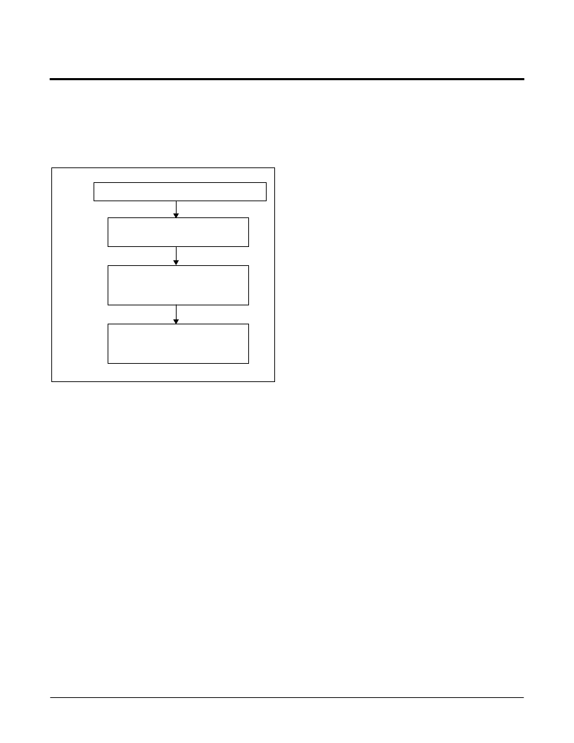
Figure 1. X76F101 Device Operation
Device Protocol
The X76F101 supports a bidirectional bus oriented
protocol. The protocol defines any device that sends data
onto the bus as a transmitter and the receiving device as
a receiver. The device controlling the transfer is a master
and the device being controlled is the slave. The master
will always initiate data transfers and provide the clock for
both transmit and receive operations. Therefore, the
X76F101 will be considered a slave in all applications.
Clock and Data Conventions
Data states on the SDA line can change only during SCL
LOW. SDA changes during SCL HIGH are reserved for
indicating start and stop conditions. Refer to Figure 2 and
Figure 3.
Start Condition
All commands are preceeded by the start condition,
which is a HIGH to LOW transition of SDA when SCL is
HIGH. The X76F101 continuously monitors the SDA and
SCL lines for the start condition and will not respond to
any command until this condition is met.
A start may be issued to terminate the input of a control
byte or the input data to be written. This will reset the
device and leave it ready to begin a new read or write
command. Because of the push/pull output, a start
cannot be generated while the part is outputting data.
Starts are inhibited while a write is in progress.
Stop Condition
All communications must be terminated by a stop
condition. The stop condition is a LOW to HIGH transition
of SDA when SCL is HIGH. The stop condition is also
used to reset the device during a command or data input
sequence and will leave the device in the standby power
mode. As with starts, stops are inhibited when outputting
data and while a write is in progress.
Acknowledge
Acknowledge is a software convention used to indicate
successful data transfer. The transmitting device, either
master or slave, will release the bus after transmitting
eight bits. During the ninth clock cycle the receiver will
pull the SDA line LOW to acknowledge that it received
the eight bits of data.
The X76F101 will respond with an acknowledge after
recognition of a start condition and its slave address. If
both the device and a write condition have been
selected, the X76F101 will respond with an acknowledge
after the receipt of each subsequent eight-bit word.
LOAD COMMAND/ADDRESS BYTE
LOAD 8-BYTE
PASSWORD
VERIFY PASSWORD
ACCEPTANCE BY
USE OF ACK POLLING
READ/WRITE
DATA
BYTES
相關(guān)PDF資料 |
PDF描述 |
|---|---|
| X76F101YI | EEPROM |
| X76F101YI-3.0 | EEPROM |
| X76F102M8-2.0 | Serial EEPROM |
| X76F102M8I-2.0 | Serial EEPROM |
| X76F102V8I-2.0 | Serial EEPROM |
相關(guān)代理商/技術(shù)參數(shù) |
參數(shù)描述 |
|---|---|
| X76F101YG | 制造商:ICMIC 制造商全稱:IC MICROSYSTEMS 功能描述:Secure SerialFlash |
| X76F101YG-3.0 | 制造商:ICMIC 制造商全稱:IC MICROSYSTEMS 功能描述:Secure SerialFlash |
| X76F101YI | 制造商:ICMIC 制造商全稱:IC MICROSYSTEMS 功能描述:Secure SerialFlash |
| X76F101YI-3.0 | 制造商:未知廠家 制造商全稱:未知廠家 功能描述:EEPROM |
| X76F101YIG | 制造商:ICMIC 制造商全稱:IC MICROSYSTEMS 功能描述:Secure SerialFlash |
發(fā)布緊急采購,3分鐘左右您將得到回復(fù)。