- 您現(xiàn)在的位置:買(mǎi)賣(mài)IC網(wǎng) > PDF目錄372926 > XPC855TZP80 Controller Miscellaneous - Datasheet Reference PDF資料下載
參數(shù)資料
| 型號(hào): | XPC855TZP80 |
| 英文描述: | Controller Miscellaneous - Datasheet Reference |
| 中文描述: | 控制器雜項(xiàng)-數(shù)據(jù)表參考 |
| 文件頁(yè)數(shù): | 12/76頁(yè) |
| 文件大小: | 825K |
| 代理商: | XPC855TZP80 |
第1頁(yè)第2頁(yè)第3頁(yè)第4頁(yè)第5頁(yè)第6頁(yè)第7頁(yè)第8頁(yè)第9頁(yè)第10頁(yè)第11頁(yè)當(dāng)前第12頁(yè)第13頁(yè)第14頁(yè)第15頁(yè)第16頁(yè)第17頁(yè)第18頁(yè)第19頁(yè)第20頁(yè)第21頁(yè)第22頁(yè)第23頁(yè)第24頁(yè)第25頁(yè)第26頁(yè)第27頁(yè)第28頁(yè)第29頁(yè)第30頁(yè)第31頁(yè)第32頁(yè)第33頁(yè)第34頁(yè)第35頁(yè)第36頁(yè)第37頁(yè)第38頁(yè)第39頁(yè)第40頁(yè)第41頁(yè)第42頁(yè)第43頁(yè)第44頁(yè)第45頁(yè)第46頁(yè)第47頁(yè)第48頁(yè)第49頁(yè)第50頁(yè)第51頁(yè)第52頁(yè)第53頁(yè)第54頁(yè)第55頁(yè)第56頁(yè)第57頁(yè)第58頁(yè)第59頁(yè)第60頁(yè)第61頁(yè)第62頁(yè)第63頁(yè)第64頁(yè)第65頁(yè)第66頁(yè)第67頁(yè)第68頁(yè)第69頁(yè)第70頁(yè)第71頁(yè)第72頁(yè)第73頁(yè)第74頁(yè)第75頁(yè)第76頁(yè)
12
MPC850 (Rev. A/B/C) Hardware Specifications
MOTOROLA
Layout Practices
Part VI Bus Signal Timing
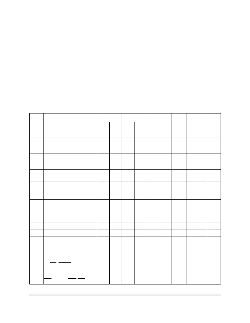
Table 6-6 provides the bus operation timing for the MPC850 at 50 MHz, 66 MHz, and 80
MHz. Timing information for other bus speeds can be interpolated by equation using the
MPC850 Electrical Specifications Spreadsheet found at http://www.mot.com/netcomm.
The maximum bus speed supported by the MPC850 is 50 MHz. Higher-speed parts must
be operated in half-speed bus mode (for example, an MPC850 used at 66 MHz must be
configured for a 33 MHz bus).
The timing for the MPC850 bus shown assumes a 50-pF load. This timing can be derated
by 1 ns per 10 pF. Derating calculations can also be performed using the MPC850 Electrical
Specifications Spreadsheet.
Table 6-6. Bus Operation Timing
1
Num
Characteristic
50 MHz
66 MHz
80 MHz
FFACT
Cap Load
(default
50 pF)
Unit
Min
Max
Min
Max
Min
Max
B1
CLKOUT period
20
—
30.30
—
25
—
—
—
ns
B1a
EXTCLK to CLKOUT phase
skew (EXTCLK > 15 MHz and
MF <= 2)
-0.90
0.90
-0.90
0.90
-0.90
0.90
—
50.00
ns
B1b
EXTCLK to CLKOUT phase
skew (EXTCLK > 10 MHz and
MF < 10)
-2.30
2.30
-2.30
2.30
-2.30
2.30
—
50.00
ns
B1c
CLKOUT phase jitter (EXTCLK
> 15 MHz and MF <= 2)
2
-0.60
0.60
-0.60
0.60
-0.60
0.60
—
50.00
ns
B1d
CLKOUT phase jitter
2
-2.00
2.00
-2.00
2.00
-2.00
2.00
—
50.00
ns
B1e
CLKOUT frequency jitter (MF <
10)
2
—
0.50
—
0.50
—
0.50
—
50.00
%
B1f
CLKOUT frequency jitter (10 <
MF < 500)
2
—
2.00
—
2.00
—
2.00
—
50.00
%
B1g
CLKOUT frequency jitter (MF >
500)
2
—
3.00
—
3.00
—
3.00
—
50.00
%
B1h
Frequency jitter on EXTCLK
3
—
0.50
—
0.50
—
0.50
—
50.00
%
B2
CLKOUT pulse width low
8.00
—
12.12
—
10.00
—
—
50.00
ns
B3
CLKOUT width high
8.00
—
12.12
—
10.00
—
—
50.00
ns
B4
CLKOUT rise time
—
4.00
—
4.00
—
4.00
—
50.00
ns
B5
CLKOUT fall time
—
4.00
—
4.00
—
4.00
—
50.00
ns
B7
CLKOUT to A[6–31],
RD/WR, BURST, D[0–31],
DP[0–3] invalid
5.00
—
7.58
—
6.25
—
0.250
50.00
ns
B7a
CLKOUT to TSIZ[0–1], REG,
RSV, AT[0–3], BDIP, PTR invalid
5.00
—
7.58
—
6.25
—
0.250
50.00
ns
相關(guān)PDF資料 |
PDF描述 |
|---|---|
| XPC860CZP50C1 | COMMUNICATIONS CONTROLLER |
| XPC860DCCZP33C1 | COMMUNICATIONS CONTROLLER |
| XPC860DCCZP50C1 | COMMUNICATIONS CONTROLLER |
| XPC860DCZP25 | Communications Controller |
| XPC860DCZP33C1 | COMMUNICATIONS CONTROLLER |
相關(guān)代理商/技術(shù)參數(shù) |
參數(shù)描述 |
|---|---|
| XPC855TZP80D4 | 制造商:MOTOROLA 制造商全稱:Motorola, Inc 功能描述:Family Hardware Specifications |
| XPC857DSLZP50B | 制造商:Freescale Semiconductor 功能描述: 制造商:Freescale Semiconductor 功能描述:MPU MPC8XX RISC 32BIT 0.32UM 50MHZ 357BGA - Trays |
| XPC857TZP100B | 制造商:Motorola Inc 功能描述: 制造商:Motorola Inc 功能描述:Communications Controller Circuit, 357 Pin, BGA |
| XPC857TZP50 | 制造商:Freescale Semiconductor 功能描述: |
| XPC860CZP33C1 | 制造商:未知廠家 制造商全稱:未知廠家 功能描述:COMMUNICATIONS CONTROLLER |
發(fā)布緊急采購(gòu),3分鐘左右您將得到回復(fù)。