- 您現(xiàn)在的位置:買賣IC網(wǎng) > PDF目錄376461 > XRT73LC00AIV (EXAR CORP) E3/DS3/STS-1 LINE INTERFACE UNIT PDF資料下載
參數(shù)資料
| 型號(hào): | XRT73LC00AIV |
| 廠商: | EXAR CORP |
| 元件分類: | 數(shù)字傳輸電路 |
| 英文描述: | E3/DS3/STS-1 LINE INTERFACE UNIT |
| 中文描述: | DATACOM, PCM TRANSCEIVER, PQFP44 |
| 封裝: | 10 X 10 MM, 1.40 MM HEIGHT, TQFP-44 |
| 文件頁(yè)數(shù): | 24/53頁(yè) |
| 文件大小: | 376K |
| 代理商: | XRT73LC00AIV |
第1頁(yè)第2頁(yè)第3頁(yè)第4頁(yè)第5頁(yè)第6頁(yè)第7頁(yè)第8頁(yè)第9頁(yè)第10頁(yè)第11頁(yè)第12頁(yè)第13頁(yè)第14頁(yè)第15頁(yè)第16頁(yè)第17頁(yè)第18頁(yè)第19頁(yè)第20頁(yè)第21頁(yè)第22頁(yè)第23頁(yè)當(dāng)前第24頁(yè)第25頁(yè)第26頁(yè)第27頁(yè)第28頁(yè)第29頁(yè)第30頁(yè)第31頁(yè)第32頁(yè)第33頁(yè)第34頁(yè)第35頁(yè)第36頁(yè)第37頁(yè)第38頁(yè)第39頁(yè)第40頁(yè)第41頁(yè)第42頁(yè)第43頁(yè)第44頁(yè)第45頁(yè)第46頁(yè)第47頁(yè)第48頁(yè)第49頁(yè)第50頁(yè)第51頁(yè)第52頁(yè)第53頁(yè)
XRT73LC00A
E3/DS3/STS-1 LINE INTERFACE UNIT
REV. P1.0.0
xr
PRELIMINARY
21
The HOST Mode
To configure the XRT73LC00A to operate in the
HOST Mode, connect the HOST/HW input pin (pin
18) to VDD.
When the XRT73LC00A is operating in the HOST
Mode, the following is true:
1.
The Microprocessor Serial Interface block is
enabled. Many configuration selections are
made by writing the appropriate data into the on-
chip Command Registers via the Microprocessor
Serial Interface.
2.
All of the following input pins are disabled:
Pin 1 - TXLEV
Pin 2 - TAOS
Pin 12 - REQDIS
Pin 14 - LLB
Pin 15 - RLB
Pin 16 - STS-1/DS3
Pin 17 - E3
Pin 35 - TXOFF
Tie each of these pins to GND if the XRT73LC00A IC
is to be operated in the HOST Mode.
Please see Section 5.0 for a detailed description on
operating the Microprocessor Serial Interface or the
on-chip Command Registers.
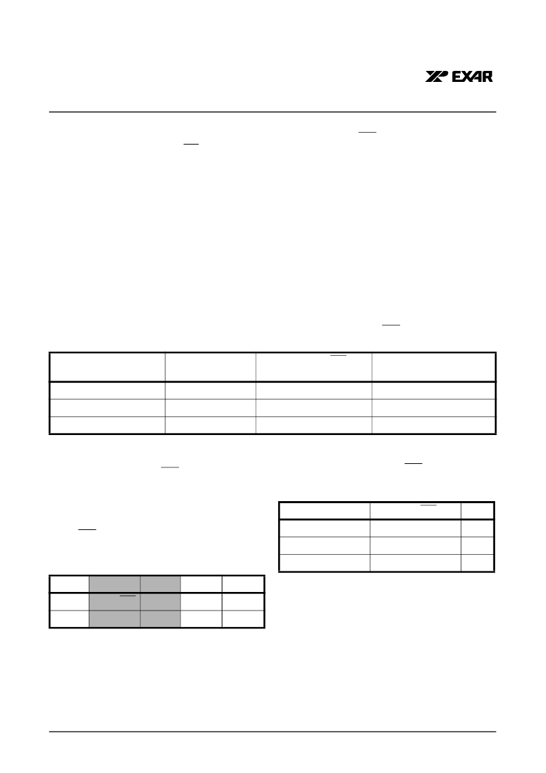
1.0
The XRT73LC00A can be configured to support the
E3 (34.368 Mbps), DS3 (44.736 Mbps) or the SONET
STS-1 (51.84 Mbps) rates. Selection of the data rate
is dependent on whether the XRT73LC00A is operat-
ing in the Hardware or HOST Mode.
SELECTING THE DATA RATE
A. When operating in the Hardware Mode.
To configure the XRT73LC00A for the desired data
rate, the E3 and the STS-1/DS3 pins must be set to
the appropriate logic states shown in Table 2.
B. When operating in the HOST Mode.
To configure the XRT73LC00A for the desired data
rate, appropriate values need to be written into the
STS-1/DS3 and E3 bit-fields in Command Register
CR4.
Table 3 relates the values of these two bit-fields with
respect to the selected data rates.
The results of making these selections are:
1.
The VCO Center Frequency of the Clock Recov-
ery Phase-Locked-Loop is configured to match
the selected data rate.
2.
The B3ZS/HDB3 Encoder and Decoder blocks
are configured to support B3ZS Encoding/Decod-
ing if the DS3 or STS-1 data rates were selected
or,
3.
The B3ZS/HDB3 Encoder and Decoder blocks
are configured to support HDB3 Encoding/
Decoding if the E3 data rate was selected.
T
ABLE
2: S
ELECTING
THE
D
ATA
R
ATE
FOR
THE
XRT73LC00A
VIA
THE
E3
AND
STS-1/DS3
INPUT
PINS
(H
ARDWARE
M
ODE
)
D
ATA
R
ATE
S
TATE
OF
E3 P
IN
(P
IN
17)
S
TATE
OF
STS-1/DS3
PIN
(P
IN
16)
M
ODE
OF
B3ZS/HDB3 E
NCODER
/
D
ECODER
B
LOCKS
E3 (34.368 Mbps)
VDD
X (Don’t Care)
HDB3
DS3 (44.736 Mbps)
0
0
B3ZS
STS-1 (51.84 Mbps)
0
VDD
B3ZS
COMMAND REGISTER CR4 (ADDRESS = 0X04)
D4
D3
D2
D1
D0
X
STS-1/DS3
E3
LLB
RLB
X
X
X
X
X
T
ABLE
3: S
ELECTING
THE
D
ATA
R
ATE
FOR
THE
XRT73LC00A V
IA
THE
STS-1/DS3
AND
THE
E3 B
IT
-
FIELDS
W
ITHIN
C
OMMAND
R
EGISTER
CR4 (HOST
M
ODE
)
S
ELECTED
D
ATA
R
ATE
STS-1/DS3
E3
E3
Don't Care
1
DS3
0
0
STS-1
1
0
相關(guān)PDF資料 |
PDF描述 |
|---|---|
| XRT73LC03A | 3 CHANNEL DS3/E3/STS-1 LINE INTERFACE UNIT |
| XRT73LC03AIV | 3 CHANNEL DS3/E3/STS-1 LINE INTERFACE UNIT |
| XRT73LC04A | 4 CHANNEL DS3/E3/STS-1 LINE INTERFACE UNIT |
| XRT73LC04AIV | 4 CHANNEL DS3/E3/STS-1 LINE INTERFACE UNIT |
| XRT73R06 | SIX CHANNEL E3/DS3/STS-1 LINE INTERFACE UNIT |
相關(guān)代理商/技術(shù)參數(shù) |
參數(shù)描述 |
|---|---|
| XRT73LC00AIV-F | 功能描述:外圍驅(qū)動(dòng)器與原件 - PCI 1-Ch DS3, E3, SONET RoHS:否 制造商:PLX Technology 工作電源電壓: 最大工作溫度: 安裝風(fēng)格:SMD/SMT 封裝 / 箱體:FCBGA-1156 封裝:Tray |
| XRT73LC00AIVTR | 功能描述:網(wǎng)絡(luò)控制器與處理器 IC RoHS:否 制造商:Micrel 產(chǎn)品:Controller Area Network (CAN) 收發(fā)器數(shù)量: 數(shù)據(jù)速率: 電源電流(最大值):595 mA 最大工作溫度:+ 85 C 安裝風(fēng)格:SMD/SMT 封裝 / 箱體:PBGA-400 封裝:Tray |
| XRT73LC00AIVTR-F | 功能描述:網(wǎng)絡(luò)控制器與處理器 IC RoHS:否 制造商:Micrel 產(chǎn)品:Controller Area Network (CAN) 收發(fā)器數(shù)量: 數(shù)據(jù)速率: 電源電流(最大值):595 mA 最大工作溫度:+ 85 C 安裝風(fēng)格:SMD/SMT 封裝 / 箱體:PBGA-400 封裝:Tray |
| XRT73LC00IV | 制造商:EXAR 制造商全稱:EXAR 功能描述:E3/DS3/STS-1 LINE INTERFACE UNIT |
| XRT73LC03A | 制造商:EXAR 制造商全稱:EXAR 功能描述:3 CHANNEL DS3/E3/STS-1 LINE INTERFACE UNIT |
發(fā)布緊急采購(gòu),3分鐘左右您將得到回復(fù)。