- 您現(xiàn)在的位置:買賣IC網(wǎng) > PDF目錄373889 > AD6426 (Analog Devices, Inc.) Enhanced GSM Processor PDF資料下載
參數(shù)資料
| 型號: | AD6426 |
| 廠商: | Analog Devices, Inc. |
| 英文描述: | Enhanced GSM Processor |
| 中文描述: | 增強(qiáng)型手機(jī)處理器 |
| 文件頁數(shù): | 24/50頁 |
| 文件大?。?/td> | 506K |
| 代理商: | AD6426 |
第1頁第2頁第3頁第4頁第5頁第6頁第7頁第8頁第9頁第10頁第11頁第12頁第13頁第14頁第15頁第16頁第17頁第18頁第19頁第20頁第21頁第22頁第23頁當(dāng)前第24頁第25頁第26頁第27頁第28頁第29頁第30頁第31頁第32頁第33頁第34頁第35頁第36頁第37頁第38頁第39頁第40頁第41頁第42頁第43頁第44頁第45頁第46頁第47頁第48頁第49頁第50頁
Preliminary Technical Information
AD6426
This Information applies to a product under development. Its characteristics and specifications are subject to change without notice. Analog Devices assumes no
obligation regarding future manufacture unless otherwise agreed to in writing. No responsibility is assumed by Analog Devices for its use; nor for any
infringements of patents or other rights of third parties which may result from its use. No license is granted by implication or otherwise under any patent or patent
rights of Analog Devices.
Revision Preliminary 2.3 (June 9, ′98)
- 24 -
Confidential Information
Rx Timing Control
RXON
The signal at the output pin RXON is generated by the
function
Receive Enable
OR
Monitor Enable
of the RADIO
CONTROL CC Control Register 2. It can be used to enable
the RF receiver and controls the RXON-pin of the AD6425. In
radios based on the Siemens solution this signal would be
connected to the RXON1 input. Additional RXON derived
signals are provided to support this solution.
Bit
RADIO CONTROL CC Control Register 2
2
Monitor Enable
1
Receive Enable
CALIBRATERADIO
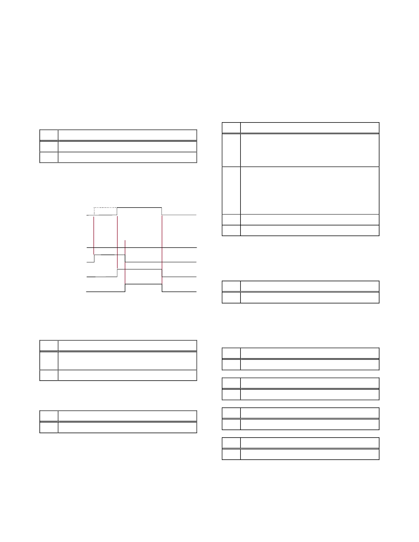
The 4 modes of the Autocalibrate signal (Type 0 & 1, AutoCal
on/off) are provided as required by the ADI or Philips solution
and shown in Figure 8.
TYPE=0, AUTOCAL=0
TYPE=0, AUTOCAL=1
TYPE=1, AUTOCAL=0
TYPE=1, AUTOCAL=1
RxEnable
Start (late)
RxEnableEnd
AutoCalibrateEnd
RxEnable
Start (early)
RXON
Figure 8. Autocalibration
The flags
Autocalibrate
and
Calibrate Radio
in the SYSTEM
CC Control Register 0 are OR′ed and connected to the output
pin CALIBRATERADIO.
Bit
the SYSTEM CC Control Register 0
7
Autocalibrate
Enables the autocalibrate function if set to 1;
3
Calibrate Radio
The type of autocalibration is set in the TRAFFIC MODE CC
Control Register 6
Bit
TRAFFIC MODE CC Control Register 6
3
Autocalibration Type
In radios based on the Siemens chipset, this signal would
connect to the RXON2 input. The required behavior is enabled
by selecting the Type 1 CalibrateRadio function.
Synthesizer Control
The radio interface of the AD6426 supports 2 dynamic
synthesizers, with each capable of downloading data on
demand.
The two
Synthesizer Load Dynamic
flags located in the
SYNTH CONTROL CC Control Register 38, will set the
synthesizer interface to load 3 consecutive long-words from
Layer 1.
Bit
SYNTH CONTROL CC Control Register 38
7
Synthesizer Enable Polarity
Selects the polarity of the SYNTHEN outputs.
If set to 0, SYNTHEN is an active low signal,
if set to 1, SYNTHEN is an active high signal.
6
Synthesizer Enable Type
Selects the active period of the SYNTHEN outputs.
When set to 0, SYTHEN is active for all data values
determined by SYNTHESIZER BIT COUNT; when
set to 1, SYNTHEN goes active after the last bit for
one SYNTHCLK period.
2
Synthesizer Load Dynamic 1 (SLD1)
1
Synthesizer Load Dynamic 0 (SLD0)
When using the
Configure Dynamic Synthesizer
flag in the
SYNTH BIT COUNT CC Control Register 37, the download-
on-demand function is applied to the synthesizer selected by
SLD0
or
SLD1
.
Bit
SYNTH BIT COUNT CC Control Register 37,
6
Configure Dynamic Synthesizer
Each dynamic synthesizer is comprised of three 32-bit word
registers, for the Rx, Tx and Monitor phases. The download
on demand uses the Rx register only for the respective
synthesizer.
Bit
SYNTHESIZER 1 CC Control Register 40
7 : 0
Synthesizer (31:24)
Bit
SYNTHESIZER 2 CC Control Register 41
7 : 0
Synthesizer (23:16)
Bit
SYNTHESIZER 3 CC Control Register 42
7 : 0
Synthesizer (15:8)
Bit
SYNTHESIZER 4 CC Control Register 43
7 : 0
Synthesizer (7:0)
相關(guān)PDF資料 |
PDF描述 |
|---|---|
| AD6426XB | DIODE, RECTIFIER, DO-201AD, AXIAL LEAD, STANDARD RECOVERY, 400 V, 3 A |
| AD6426XST | 1N5817 DIODE SCHOTTKY 20V 1A DO-41 |
| AD642J | Precision, Low Cost Dual BiFET Op Amp |
| AD642K | SCHOTTKY DIODE DO-204AL 40V 1A |
| AD642L | Precision, Low Cost Dual BiFET Op Amp |
相關(guān)代理商/技術(shù)參數(shù) |
參數(shù)描述 |
|---|---|
| AD6426XB | 制造商:AD 制造商全稱:Analog Devices 功能描述:Enhanced GSM Processor |
| AD6426XST | 制造商:AD 制造商全稱:Analog Devices 功能描述:Enhanced GSM Processor |
| AD642J | 制造商:AD 制造商全稱:Analog Devices 功能描述:Precision, Low Cost Dual BiFET Op Amp |
| AD642JH | 制造商:Rochester Electronics LLC 功能描述:PRECISION DUAL OP AMP IC - Bulk |
| AD642K | 制造商:AD 制造商全稱:Analog Devices 功能描述:Precision, Low Cost Dual BiFET Op Amp |
發(fā)布緊急采購,3分鐘左右您將得到回復(fù)。