- 您現(xiàn)在的位置:買賣IC網(wǎng) > PDF目錄373891 > AD6655BCPZ-1051 (Analog Devices, Inc.) IF Diversity Receiver PDF資料下載
參數(shù)資料
| 型號(hào): | AD6655BCPZ-1051 |
| 廠商: | Analog Devices, Inc. |
| 英文描述: | IF Diversity Receiver |
| 中文描述: | IF分集接收機(jī) |
| 文件頁數(shù): | 43/84頁 |
| 文件大小: | 2012K |
| 代理商: | AD6655BCPZ-1051 |
第1頁第2頁第3頁第4頁第5頁第6頁第7頁第8頁第9頁第10頁第11頁第12頁第13頁第14頁第15頁第16頁第17頁第18頁第19頁第20頁第21頁第22頁第23頁第24頁第25頁第26頁第27頁第28頁第29頁第30頁第31頁第32頁第33頁第34頁第35頁第36頁第37頁第38頁第39頁第40頁第41頁第42頁當(dāng)前第43頁第44頁第45頁第46頁第47頁第48頁第49頁第50頁第51頁第52頁第53頁第54頁第55頁第56頁第57頁第58頁第59頁第60頁第61頁第62頁第63頁第64頁第65頁第66頁第67頁第68頁第69頁第70頁第71頁第72頁第73頁第74頁第75頁第76頁第77頁第78頁第79頁第80頁第81頁第82頁第83頁第84頁
AD6655
Increment Gain (IG) and Decrement Gain (DG)
The increment gain and decrement gain indicators are intended
to be used together to provide information to enable external
gain control. The decrement gain indicator works in conjunction
with the coarse upper threshold bits, asserting when the input
magnitude is greater than the 3-bit value in the coarse upper
threshold register (Address 0x105). The increment gain indicator,
similarly, corresponds to the fine lower threshold bits except
that it is asserted only if the input magnitude is less than the
value programmed in the fine lower threshold register after the
dwell time elapses. The dwell time is set by the 16-bit dwell time
value located at Address 0x10A and Address 0x10B and is set in
units of ADC input clock cycles ranging from 1 to 65,535. The
fine lower threshold register is a 13-bit register that is compared
Rev. 0 | Page 43 of 84
with the magnitude at the output of the ADC. This comparison
is subject to the ADC clock latency but allows a finer, more
accurate comparison. The fine upper threshold magnitude is
defined by the following equation:
dBFS
= 20 log(
Threshold Magnitude
/2
13
)
The decrement gain output works from the ADC fast detect
output pins, providing a fast indication of potential overrange
conditions. The increment gain uses the comparison at the
output of the ADC, requiring the input magnitude to remain
below an accurate, programmable level for a predefined period
before signaling external circuitry to increase the gain.
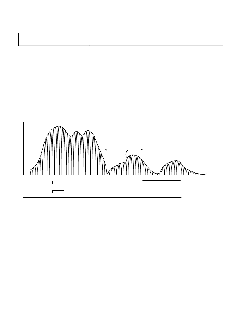
The operation of the increment gain output and decrement gain
output is shown graphically in Figure 75.
UPPER THRESHOLD (COARSE OR FINE)
FINE LOWER THRESHOLD
IG
DG
F_LT
C_UT OR F_UT*
DWELL TIME
TIMER RESET BY
RISE ABOVE F_LT
TIMER COMPLETES BEFORE
SIGNAL RISES ABOVE F_LT
NOTE: OUTPUTS FOLLOW THE INSTANTEOUS SIGNAL LEVEL AND NOT THE ENVELOPE BUT ARE GUARANTEED ACTIVE FOR A MINIMUM OF 2 ADC CLOCK CYCLES.
Figure 75. Threshold Settings for C_UT, F_UT, F_LT, DG, and IG
*C_UT AND F_UT DIFFER ONLY IN ACCURACY AND LATENCY.
DWELL TIME
0
相關(guān)PDF資料 |
PDF描述 |
|---|---|
| AD6655BCPZ-1501 | IF Diversity Receiver |
| AD6655BCPZ-801 | IF Diversity Receiver |
| AD667JN | Microprocessor-Compatible 12-Bit D/A Converter |
| AD667JP | Microprocessor-Compatible 12-Bit D/A Converter |
| AD667KN | Microprocessor-Compatible 12-Bit D/A Converter |
相關(guān)代理商/技術(shù)參數(shù) |
參數(shù)描述 |
|---|---|
| AD6655BCPZ-125 | 制造商:Analog Devices 功能描述:IF Diversity Receiver 64-Pin LFCSP EP 制造商:Analog Devices 功能描述:IC RECEIVER IF DIVERSITY LFCSP64 |
| AD6655BCPZ-125 | 制造商:Analog Devices 功能描述:Communication IC |
| AD6655BCPZ-1251 | 制造商:AD 制造商全稱:Analog Devices 功能描述:IF Diversity Receiver |
| AD6655BCPZ-150 | 制造商:Analog Devices 功能描述:IF Diversity Receiver 64-Pin LFCSP EP 制造商:Analog Devices 功能描述:IC RECEIVER IF DIVERSITY LFCSP64 |
| AD6655BCPZ-150 | 制造商:Analog Devices 功能描述:Communication IC |
發(fā)布緊急采購,3分鐘左右您將得到回復(fù)。