- 您現(xiàn)在的位置:買賣IC網(wǎng) > PDF目錄373891 > AD6655BCPZ-1501 (Analog Devices, Inc.) IF Diversity Receiver PDF資料下載
參數(shù)資料
| 型號(hào): | AD6655BCPZ-1501 |
| 廠商: | Analog Devices, Inc. |
| 英文描述: | IF Diversity Receiver |
| 中文描述: | IF分集接收機(jī) |
| 文件頁(yè)數(shù): | 37/84頁(yè) |
| 文件大小: | 2012K |
| 代理商: | AD6655BCPZ-1501 |
第1頁(yè)第2頁(yè)第3頁(yè)第4頁(yè)第5頁(yè)第6頁(yè)第7頁(yè)第8頁(yè)第9頁(yè)第10頁(yè)第11頁(yè)第12頁(yè)第13頁(yè)第14頁(yè)第15頁(yè)第16頁(yè)第17頁(yè)第18頁(yè)第19頁(yè)第20頁(yè)第21頁(yè)第22頁(yè)第23頁(yè)第24頁(yè)第25頁(yè)第26頁(yè)第27頁(yè)第28頁(yè)第29頁(yè)第30頁(yè)第31頁(yè)第32頁(yè)第33頁(yè)第34頁(yè)第35頁(yè)第36頁(yè)當(dāng)前第37頁(yè)第38頁(yè)第39頁(yè)第40頁(yè)第41頁(yè)第42頁(yè)第43頁(yè)第44頁(yè)第45頁(yè)第46頁(yè)第47頁(yè)第48頁(yè)第49頁(yè)第50頁(yè)第51頁(yè)第52頁(yè)第53頁(yè)第54頁(yè)第55頁(yè)第56頁(yè)第57頁(yè)第58頁(yè)第59頁(yè)第60頁(yè)第61頁(yè)第62頁(yè)第63頁(yè)第64頁(yè)第65頁(yè)第66頁(yè)第67頁(yè)第68頁(yè)第69頁(yè)第70頁(yè)第71頁(yè)第72頁(yè)第73頁(yè)第74頁(yè)第75頁(yè)第76頁(yè)第77頁(yè)第78頁(yè)第79頁(yè)第80頁(yè)第81頁(yè)第82頁(yè)第83頁(yè)第84頁(yè)
AD6655
DIGITAL DOWNCONVERTER
The AD6655 includes a digital processing section that provides
filtering and reduces the output data rate. This digital processing
section includes a numerically controlled oscillator (NCO),
a half-band decimating filter, an FIR filter, and a second coarse
NCO (f
ADC
/8 fixed value) for output frequency translation. Each
of these processing blocks (except the decimating half-band
filter) has control lines that allow it to be independently enabled
and disabled to provide the desired processing function. The
digital downconverter can be configured to output either real data
or complex output data. These blocks can be configured in five
recommended combinations to implement different signal
processing functions.
DOWNCONVERTER MODES
Table 18 details the recommended downconverter modes of
operation in the AD6655.
Rev. 0 | Page 37 of 84
Table 18. Downconverter Modes
Mode
NCO/Filter
1
Half-band filter only
2
Half-band filter and FIR filter
3
NCO and half-band filter
4
NCO, half-band filter, and FIR filter
5
NCO, half-band filter, FIR filter, and
f
ADC
/8 NCO
NUMERICALLY CONTROLLED OSCILLATOR (NCO)
Frequency translation is accomplished with an NCO. Each of
the two processing channels shares a common NCO. Amplitude
and phase dither can be enabled on chip to improve the noise and
spurious performance of the NCO. A phase offset word is available
to create a known phase relationship between multiple AD6655s.
Because the decimation filter prevents usage of half the Nyquist
spectrum, a means is needed to translate the sampled input
spectrum into the usable range of the decimation filter. To
achieve this, a 32-bit, fine tuning, complex NCO is provided.
This NCO/mixer allows the input spectrum to be tuned to dc,
where it can be effectively filtered by the subsequent filter
blocks to prevent aliasing.
HALF-BAND DECIMATING FILTER AND FIR FILTER
The goal of the AD6655 digital filter block is to allow the sample
rate to be reduced by a factor of 2 while rejecting aliases that fall
into the band of interest. The half-band filter is designed to operate
as either a low-pass or high-pass filter and to provide greater
than 100 dB of alias protection for 22% of the input rate of the
structure. For an ADC sample rate of 150 MSPS, this provides
Output Type
Real
Real
Complex
Complex
Real
a maximum usable bandwidth of 16.5 MHz when using the filter
in real mode (NCO bypassed) or a maximum usable bandwidth
of 33.0 MHz when using the filter in the complex mode (NCO
enabled).
The optional fixed-coefficient FIR filter provides additional
filtering capability to sharpen the half-band roll-off to enhance
the alias protection. It removes the negative frequency images
to avoid aliasing negative frequencies for real outputs.
f
ADC
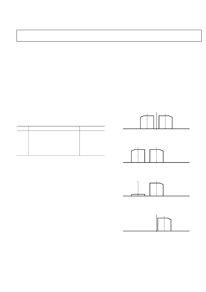
/8 FIXED-FREQUENCY NCO
A fixed f
ADC
/8 NCO is provided to translate the filtered, decimated
signal from dc to f
ADC
/8 to allow a real output. Figure 68 to
Figure 71 show an example of a 20 MHz input as it is processed
by the blocks of the AD6655.
–50
–24
–14
14
24
50
–4
4
0
0
Figure 68. Example AD6655 Real 20 MHz Bandwidth Input Signal Centered at
14 MHz (f
ADC
= 100 MHz)
–50
–38
–28
0
10
50
–18 –10
0
Figure 69. Example AD6655 20 MHz Bandwidth Input Signal Tuned to DC
Using the NCO (NCO Frequency = 14 MHz)
–50
Figure 70. Example AD6655 20 MHz Bandwidth Input Signal wth the
Negative Image Filtered by the Half-Band and FIR Filters
–38
–28
0
10
50
–18 –10
0
–50
Figure 71. Example AD6655 20 MHz Bandwidth Input Signal Tuned to
f
ADC
/8 for Real Output
0.25
22.5
12.5
50
0
相關(guān)PDF資料 |
PDF描述 |
|---|---|
| AD6655BCPZ-801 | IF Diversity Receiver |
| AD667JN | Microprocessor-Compatible 12-Bit D/A Converter |
| AD667JP | Microprocessor-Compatible 12-Bit D/A Converter |
| AD667KN | Microprocessor-Compatible 12-Bit D/A Converter |
| AD667KP | Microprocessor-Compatible 12-Bit D/A Converter |
相關(guān)代理商/技術(shù)參數(shù) |
參數(shù)描述 |
|---|---|
| AD6655BCPZ-80 | 制造商:Analog Devices 功能描述:IF Diversity Receiver 64-Pin LFCSP EP 制造商:Analog Devices 功能描述:IC RECEIVER IF DIVERSITY LFCSP64 |
| AD6655BCPZ-80 | 制造商:Analog Devices 功能描述:Communication IC |
| AD6655BCPZ-801 | 制造商:AD 制造商全稱:Analog Devices 功能描述:IF Diversity Receiver |
| AD6655BCPZRL7-125 | 制造商:Analog Devices 功能描述: |
| AD6655BCPZRL7-150 | 制造商:Analog Devices 功能描述: 制造商:Rochester Electronics LLC 功能描述: |
發(fā)布緊急采購(gòu),3分鐘左右您將得到回復(fù)。