- 您現(xiàn)在的位置:買賣IC網(wǎng) > PDF目錄362157 > AG302-63-RFID InGaP HBT Gain Block PDF資料下載
參數(shù)資料
| 型號: | AG302-63-RFID |
| 英文描述: | InGaP HBT Gain Block |
| 中文描述: | InGaP HBT增益模塊 |
| 文件頁數(shù): | 5/6頁 |
| 文件大小: | 543K |
| 代理商: | AG302-63-RFID |
Specifications and information are subject to change without notice
WJ Communications, Inc
Phone 1-800-WJ1-4401
FAX: 408-577-6621
e-mail: sales@wj.com
Web site: www.wj.com
Page 5 of 6 July 2005
AG302-63
InGaP HBT Gain Block
Product Information
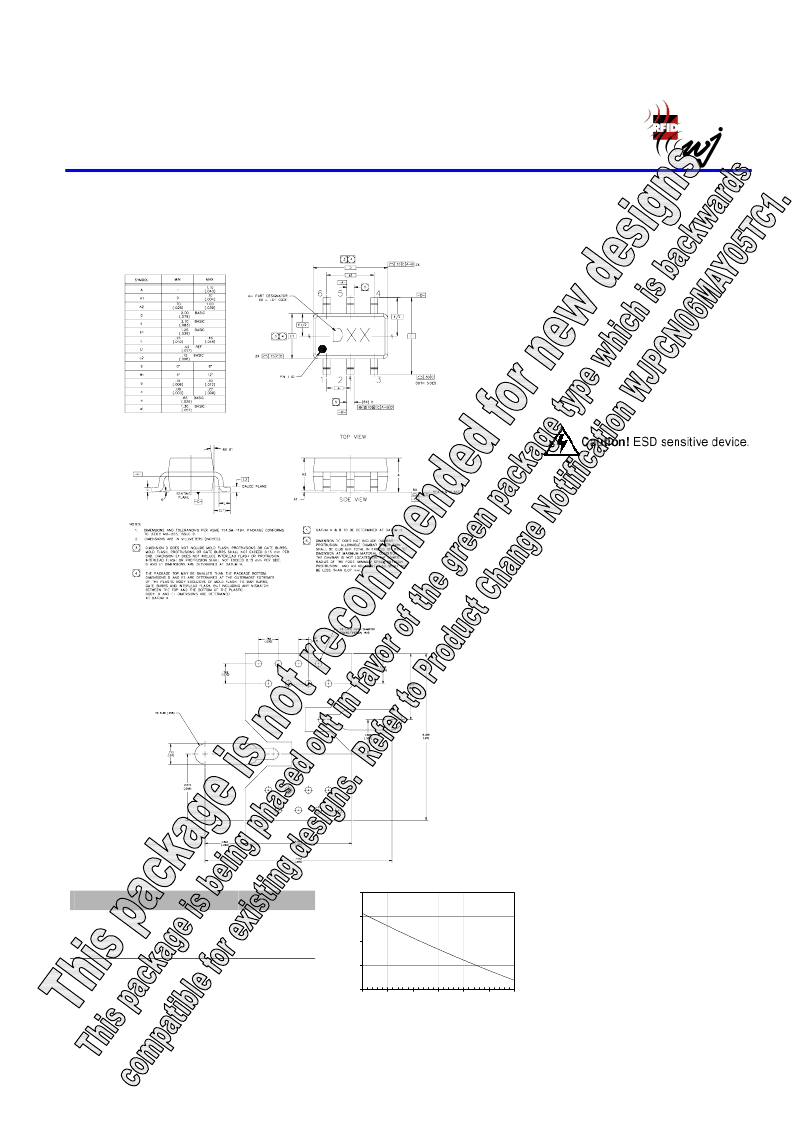
AG302-63 (SOT-363 Package) Mechanical Information
This package may contain lead-bearing materials. The plating material on the leads is SnPb
.
Outline Drawing
Land Pattern
Thermal Specifications
Parameter
Operating Case Temperature
(1)
Junction Temperature, Tjc
(2)
1. The thermal resistance is referenced from the hottest part
of the junction to the ground pin (pin 4).
2. This corresponds to the typical biasing condition of
+4.23V, 35 mA at an 85
°
C case temperature. A
minimum MTTF of 1 million hours is achieved for
junction temperatures below 177
°
C.
Rating
-40 to +85
°
C
325
°
C/W
133
°
C
Product Marking
The component will be marked with a “D”
designator followed by a two-digit numeric
lot code on the top surface of the package.
Tape and reel specifications for this part are
located on the website in the “Application
Notes” section.
MSL / ESD Rating
ESD Rating: Class 0
Value:
Test:
Standard:
ESD Rating: Class II
Value:
Test:
Standard:
MSL Rating: Level 1
Standard:
Mounting Config. Notes
Passes at 150 V
Human Body Model (HBM)
JEDEC Standard JESD22-A114
Passes at 250 V
Charged Device Model (CDM)
JEDEC Standard JESD22-C101
JEDEC Standard J-STD-020
1. Ground / thermal vias are critical for the proper performance
of this device. Vias should use a .35mm (#80 / .0135”)
diameter drill and have a final plated thru diameter of .25 mm
(.010”).
2. Add as much copper as possible to inner and outer layers near
the part to ensure optimal thermal performance.
3. Mounting screws can be added near the part to fasten the
board to a heatsink. Ensure that the ground / thermal via
region contacts the heatsink.
4. Do not put solder mask on the backside of the PC board in the
region where the board contacts the heatsink.
5. RF trace width depends upon the PC board material and
construction.
6. Use 1 oz. Copper minimum.
7. All dimensions are in millimeters (inches). Angles are in
degrees.
MTTF vs. GND Lead Temperature
1
10
100
1000
10000
60
70
80
90
100
110
120
Ground Lead Temperature (°C)
M
相關(guān)PDF資料 |
PDF描述 |
|---|---|
| AG302-86G | InGaP HBT Gain Block |
| AG303-63G | InGaP HBT Gain Block |
| AG303-86G | InGaP HBT Gain Block |
| AG303-86-RFID | InGaP HBT Gain Block |
| AG402-86G | InGaP HBT Gain Block |
相關(guān)代理商/技術(shù)參數(shù) |
參數(shù)描述 |
|---|---|
| AG302-63TRG | 制造商:TriQuint Semiconductor 功能描述:GAIN BLOCK 制造商:TriQuint Semiconductor 功能描述:AG302-63TRG |
| AG302-86 | 制造商:未知廠家 制造商全稱:未知廠家 功能描述:InGaP HBT Gain Block |
| AG302-86G | 功能描述:射頻放大器 DC-6000MHz 15.5dB Gain@900MHz RoHS:否 制造商:Skyworks Solutions, Inc. 類型:Low Noise Amplifier 工作頻率:2.3 GHz to 2.8 GHz P1dB:18.5 dBm 輸出截獲點:37.5 dBm 功率增益類型:32 dB 噪聲系數(shù):0.85 dB 工作電源電壓:5 V 電源電流:125 mA 測試頻率:2.6 GHz 最大工作溫度:+ 85 C 安裝風(fēng)格:SMD/SMT 封裝 / 箱體:QFN-16 封裝:Reel |
| AG302-86PCB | 功能描述:射頻開發(fā)工具 700-2400MHz Eval Brd 13.5dBm 15.5dB Gain RoHS:否 制造商:Taiyo Yuden 產(chǎn)品:Wireless Modules 類型:Wireless Audio 工具用于評估:WYSAAVDX7 頻率: 工作電源電壓:3.4 V to 5.5 V |
| AG302-86TRG | 制造商:TriQuint Semiconductor 功能描述:GAIN BLOCK |
發(fā)布緊急采購,3分鐘左右您將得到回復(fù)。