- 您現(xiàn)在的位置:買(mǎi)賣(mài)IC網(wǎng) > PDF目錄362197 > AK7716VT Consumer IC PDF資料下載
參數(shù)資料
| 型號(hào): | AK7716VT |
| 英文描述: | Consumer IC |
| 中文描述: | 消費(fèi)性IC |
| 文件頁(yè)數(shù): | 27/60頁(yè) |
| 文件大小: | 1171K |
| 代理商: | AK7716VT |
第1頁(yè)第2頁(yè)第3頁(yè)第4頁(yè)第5頁(yè)第6頁(yè)第7頁(yè)第8頁(yè)第9頁(yè)第10頁(yè)第11頁(yè)第12頁(yè)第13頁(yè)第14頁(yè)第15頁(yè)第16頁(yè)第17頁(yè)第18頁(yè)第19頁(yè)第20頁(yè)第21頁(yè)第22頁(yè)第23頁(yè)第24頁(yè)第25頁(yè)第26頁(yè)當(dāng)前第27頁(yè)第28頁(yè)第29頁(yè)第30頁(yè)第31頁(yè)第32頁(yè)第33頁(yè)第34頁(yè)第35頁(yè)第36頁(yè)第37頁(yè)第38頁(yè)第39頁(yè)第40頁(yè)第41頁(yè)第42頁(yè)第43頁(yè)第44頁(yè)第45頁(yè)第46頁(yè)第47頁(yè)第48頁(yè)第49頁(yè)第50頁(yè)第51頁(yè)第52頁(yè)第53頁(yè)第54頁(yè)第55頁(yè)第56頁(yè)第57頁(yè)第58頁(yè)第59頁(yè)第60頁(yè)
[ASAHI KASEI]
[AK7716]
<M0057-E-01>
1999/09
- 27 -
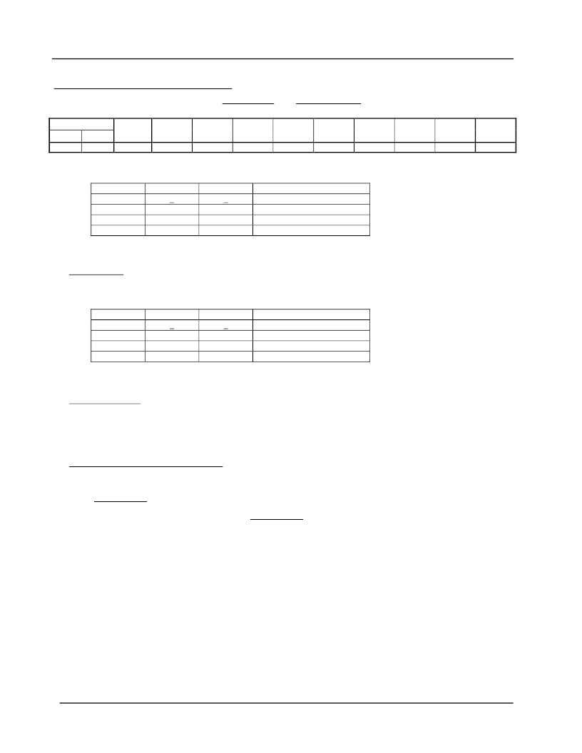
2-1) CONT0 : clock and interface selector
This register is enable only at system reset state ( DSP_RESET =”L”, CODEC_RESET =”L”)
Command Code
Write
Read
Name
D7
D6
D5
D4
D3
D2
D1
D0
Default
60h
70h
CONT0
CKS1
CKS0
DIF
DIF1
DIF0
DISCK
SELCKO
X
00h
D7,D6: Master clock selector
Mode
1
2
3
4
D7
0
0
1
1
D6
0
1
0
1
512fs
384fs
TEST mode (Don’t use).
256fs
D5:DIF Audio interface selector
0:AKM method
1: I2S compatible ( In this case, all input / output pins are I2S compatible.)
D4,D3:DIF1,DIF0 SDIN1,SDIN2 Input mode selector
Mode
1
2
3
4
Note) When D5= 1, the state is I2S compatible independently of mode setting, however set to Mode 1.
D4
0
0
1
1
D3
0
1
0
1
MSB justified (24bit)
LSB justified (24bit)
LSB justified (20bit)
LSB justified (16bit)
D2:DISCK LRCLK,BITCLKOutput control
0: Normal Operation
1: This setting can fix BITCLK=”L” and LRCLK=”H” at master mode.
(Note In case of I2S compatible setting, it become LRCLK=”L”.)
This setting is available only for use the AK7716 analog input and analog output.
D1:SELCKO CLKO Output selector.
0:CLKO outputs the same frequency as XTI.
1:CLKO outputs 1/2 frequency of XTI.
Note) In the case of select 1, after setting CONT0 (when the last clock of SCLK rise up) CLKO will change its frequency.
So, the click noise comes out at this change.
Until INIT_RESET changes to ”L” or changes control register, the output frequency does not change.
Phase matching between CLKO and XTI is done at INIT_RESET =”L”.
D0: Always 0
Note) Underlines of the setting of
~
mean default setting.
相關(guān)PDF資料 |
PDF描述 |
|---|---|
| AK80A-024L-033F40 | Analog IC |
| AK80A-024L-050F30 | Analog IC |
| AK80A-024L-120F14 | Analog IC |
| AK80A-024L-150F12 | Analog IC |
| AK80A-024L-240F08 | Analog IC |
相關(guān)代理商/技術(shù)參數(shù) |
參數(shù)描述 |
|---|---|
| AK7719 | 制造商:AKM 制造商全稱(chēng):AKM 功能描述:Low Power DSP for Voice and Audio Processing |
| AK7719B | 制造商:AKM 制造商全稱(chēng):AKM 功能描述:Low Power DSP for Voice and Audio Processing |
| AK7719BECB | 制造商:AKM 制造商全稱(chēng):AKM 功能描述:Low Power DSP for Voice and Audio Processing |
| AK7719ECB | 制造商:AKM 制造商全稱(chēng):AKM 功能描述:Low Power DSP for Voice and Audio Processing |
| AK7720AVTP | 制造商:AKM Semiconductor Inc 功能描述:AK7720AVTP |
發(fā)布緊急采購(gòu),3分鐘左右您將得到回復(fù)。