- 您現(xiàn)在的位置:買賣IC網(wǎng) > PDF目錄366550 > AM79C972BKCW (ADVANCED MICRO DEVICES INC) PCnet⑩-FAST+ Enhanced 10/100 Mbps PCI Ethernet Controller with OnNow Support PDF資料下載
參數(shù)資料
| 型號: | AM79C972BKCW |
| 廠商: | ADVANCED MICRO DEVICES INC |
| 元件分類: | 微控制器/微處理器 |
| 英文描述: | PCnet⑩-FAST+ Enhanced 10/100 Mbps PCI Ethernet Controller with OnNow Support |
| 中文描述: | 5 CHANNEL(S), 100M bps, LOCAL AREA NETWORK CONTROLLER, PQFP16 |
| 封裝: | PLASTIC, QFP-160 |
| 文件頁數(shù): | 61/130頁 |
| 文件大小: | 1580K |
| 代理商: | AM79C972BKCW |
第1頁第2頁第3頁第4頁第5頁第6頁第7頁第8頁第9頁第10頁第11頁第12頁第13頁第14頁第15頁第16頁第17頁第18頁第19頁第20頁第21頁第22頁第23頁第24頁第25頁第26頁第27頁第28頁第29頁第30頁第31頁第32頁第33頁第34頁第35頁第36頁第37頁第38頁第39頁第40頁第41頁第42頁第43頁第44頁第45頁第46頁第47頁第48頁第49頁第50頁第51頁第52頁第53頁第54頁第55頁第56頁第57頁第58頁第59頁第60頁當前第61頁第62頁第63頁第64頁第65頁第66頁第67頁第68頁第69頁第70頁第71頁第72頁第73頁第74頁第75頁第76頁第77頁第78頁第79頁第80頁第81頁第82頁第83頁第84頁第85頁第86頁第87頁第88頁第89頁第90頁第91頁第92頁第93頁第94頁第95頁第96頁第97頁第98頁第99頁第100頁第101頁第102頁第103頁第104頁第105頁第106頁第107頁第108頁第109頁第110頁第111頁第112頁第113頁第114頁第115頁第116頁第117頁第118頁第119頁第120頁第121頁第122頁第123頁第124頁第125頁第126頁第127頁第128頁第129頁第130頁

Am79C972
61
padding feature. The pad is placed between the LLC
data field and FCS field in the IEEE 802.3 frame. FCS
is always added if the frame is padded, regardless of
the state of DXMTFCS (CSR15, bit 3) or ADD_FCS
(TMD1, bit 29). The transmit frame will be padded by
bytes with the value of 00H. The default value of
APAD_XMT is 0, which will disable automatic pad gen-
eration after H_RESET.
It is the responsibility of upper layer software to cor-
rectly define the actual length field contained in the
message to correspond to the total number of LLC
Data bytes encapsulated in the frame (length field as
defined in the ISO 8802-3 (IEEE/ANSI 802.3) stan-
dard). The length value contained in the message is not
used by the Am79C972 controller to compute the ac-
tual number of pad bytes to be inserted. The
Am79C972 controller will append pad bytes dependent
on the actual number of bits transmitted onto the net-
work. Once the last data byte of the frame has com-
pleted, prior to appending the FCS, the Am79C972
controller will check to ensure that 544 bits have been
transmitted. If not, pad bytes are added to extend the
frame size to this value, and the FCS is then added.
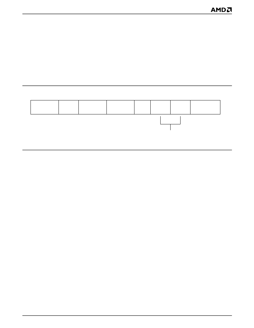
See Figure 33.
.
Figure 33.
ISO 8802-3 (IEEE/ANSI 802.3) Data Frame
The 544 bit count is derived from the following:
Minimum frame size (excluding preamble/SFD,
including FCS)
64 bytes
512 bits
Preamble/SFD size 8 bytes
64 bits
FCS size
4 bytes
32 bits
At the point that FCS is to be appended, the transmitted
frame should contain:
Preamble/SFD + (Min Frame Size - FCS)
64 + (512-32) = 544 bits
A minimum length transmit frame from the Am79C972
controller, therefore, will be 576 bits, after the FCS is
appended.
Transmit FCS Generation
Automatic generation and transmission of FCS for a
transmit frame depends on the value of DXMTFCS
(CSR15, bit 3). If DXMTFCS is cleared to 0, the trans-
mitter will generate and append the FCS to the trans-
mitted frame. If the automatic padding feature is
invoked (APAD_XMT is set in CSR4), the FCS will be
appended to frames shorter than 64 bytes by the
Am79C972 controller regardless of the state of DXMT-
FCS or ADD_FCS (TMD1, bit 29). Note that the calcu-
lated FCS is transmitted most significant bit first. The
default value of DXMTFCS is 0 after H_RESET.
ADD_FCS (TMD1, bit 29) allows the automatic gener-
ation and transmission of FCS on a frame-by-frame
basis. DXMTFCS should be set to 1 in this mode. To
generate FCS for a frame, ADD_FCS must be set in all
descriptors of a frame (STP is set to 1). Note that bit 29
of TMD1 has the function of ADD_FCS if SWSTYLE
(BCR20, bits 7-0) is programmed to 0, 2, or 3.
Transmit Exception Conditions
Exception conditions for frame transmission fall into
two distinct categories: those conditions which are the
result of normal network operation, and those which
occur due to abnormal network and/or host related
events.
Normal events which may occur and which are handled
autonomously by the Am79C972 controller include col-
lisions within the slot time with automatic retry. The
Am79C972 controller will ensure that collisions which
occur within 512 bit times from the start of transmission
(including preamble) will be automatically retried with
no host intervention. The transmit FIFO ensures this by
guaranteeing that data contained within the FIFO will
not be overwritten until at least 64 bytes (512 bits) of
preamble plus address, length, and data fields have
been transmitted onto the network without encounter-
ing a collision. Note that if DRTY (CSR15, bit 5) is set
to 1 or if the network interface is operating in full-duplex
mode, no collision handling is required, and any byte of
Preamble
1010....1010
SFD
10101011
Destination
Address
Source
Address
Length
LLC
Data
Pad
FCS
4
Bytes
46
—
1500
Bytes
2
Bytes
6
Bytes
6
Bytes
8
Bits
56
Bits
21485C-36
相關(guān)PDF資料 |
PDF描述 |
|---|---|
| AM79C972BKIW | PCnet⑩-FAST+ Enhanced 10/100 Mbps PCI Ethernet Controller with OnNow Support |
| AM79C972BVCW | PCnet⑩-FAST+ Enhanced 10/100 Mbps PCI Ethernet Controller with OnNow Support |
| AM79C972 | PCnet⑩-FAST+ Enhanced 10/100 Mbps PCI Ethernet Controller with OnNow Support |
| AM79C972BVIW | PCnet⑩-FAST+ Enhanced 10/100 Mbps PCI Ethernet Controller with OnNow Support |
| AM79C974 | PCnetTM-SCSI Combination Ethernet and SCSI Controller for PCI Systems |
相關(guān)代理商/技術(shù)參數(shù) |
參數(shù)描述 |
|---|---|
| AM79C972BKD/W | 制造商:Advanced Micro Devices 功能描述: |
| AM79C972BKD\\W | 制造商:Advanced Micro Devices 功能描述: |
| AM79C972BKD\W | 制造商:Advanced Micro Devices 功能描述: |
| AM79C972BKIW | 制造商:AMD 制造商全稱:Advanced Micro Devices 功能描述:PCnet⑩-FAST+ Enhanced 10/100 Mbps PCI Ethernet Controller with OnNow Support |
| AM79C972BVC | 制造商:Advanced Micro Devices 功能描述: |
發(fā)布緊急采購,3分鐘左右您將得到回復(fù)。