- 您現(xiàn)在的位置:買賣IC網(wǎng) > PDF目錄362306 > AMD-K5 AMD-K5 Processor Thermal Considerations Application Note PDF資料下載
參數(shù)資料
| 型號: | AMD-K5 |
| 英文描述: | AMD-K5 Processor Thermal Considerations Application Note |
| 中文描述: | AMD的K5處理器散熱考慮應(yīng)用筆記 |
| 文件頁數(shù): | 21/44頁 |
| 文件大小: | 2886K |
| 代理商: | AMD-K5 |
第1頁第2頁第3頁第4頁第5頁第6頁第7頁第8頁第9頁第10頁第11頁第12頁第13頁第14頁第15頁第16頁第17頁第18頁第19頁第20頁當(dāng)前第21頁第22頁第23頁第24頁第25頁第26頁第27頁第28頁第29頁第30頁第31頁第32頁第33頁第34頁第35頁第36頁第37頁第38頁第39頁第40頁第41頁第42頁第43頁第44頁
Thermal Interfaces
13
20092B/0—Sep1996
AMD-K5 Processor Thermal Considerations
Thermal Interfaces
Thermal interface between the case and heat sink is controlled
in a variety of ways using different heat conducting materials.
The interface resistance between the case and the heat sink is
dependent on three variables: p (the thermal resistance of the
interface material in units of (
o
C · inch
2
) / (watts · thickness in
inches)), t (the average material thickness in inches), and A
(the area of contact in square inches). These variables are
related in the following equation:
Equation 5
θ
cs
= (p · t ) / A
Table 2 contains typical thermal resistance values for materi-
als used in cooling solutions for semiconductors.
The thermal interface material is placed between the top of
the AMD-K5 processor case and the bottom plate of the heat
sink. It is recommended that the heat sink plate have a flatness
tolerance of 0.002
′′
to 0.003
′′
per inch. The thickness of the
thermal interface material should be minimized to obtain the
lowest possible thermal resistance. The thermal grease com-
pounds are the best materials for the thermal interface, fol-
lowed by thermal compounds, and then thermal adhesive
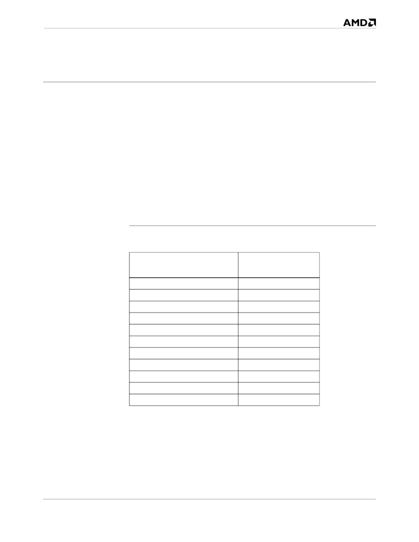
Table 2. Thermal Conductivity Values for Materials Used In Cooling
Solutions
Thermal Interface Materials
Thermal Conductivity
(Watts / (Meter ·
o
C)
389
200
220
240
60.5
21
0.5-1.0
0.2
0.15
0.5-1.0
0.026
Copper (pure)
Aluminum (1100 series)
Aluminum (6000 series)
Beryllia
Carbon Steel
Alumina
Anodized Finish
Silicone RTV
Polyimide
Silicone Grease
Dead Air
相關(guān)PDF資料 |
PDF描述 |
|---|---|
| AMD-K5-PR100ABQ | 32-Bit Microprocessor |
| AMD-K5-PR120ABR | 32-Bit Microprocessor |
| AMD-K5-PR133ABQ | 32-Bit Microprocessor |
| AMD-K5-PR133ABR | 32-Bit Microprocessor |
| AMD-K5-PR166ABX | 32-Bit Microprocessor |
相關(guān)代理商/技術(shù)參數(shù) |
參數(shù)描述 |
|---|---|
| AMD-K5-PR100ABQ | 制造商:未知廠家 制造商全稱:未知廠家 功能描述:32-Bit Microprocessor |
| AMD-K5-PR120ABR | 制造商:未知廠家 制造商全稱:未知廠家 功能描述:32-Bit Microprocessor |
| AMD-K5-PR133ABQ | 制造商:未知廠家 制造商全稱:未知廠家 功能描述:32-Bit Microprocessor |
| AMD-K5-PR133ABR | 制造商:未知廠家 制造商全稱:未知廠家 功能描述:32-Bit Microprocessor |
| AMD-K5-PR166ABX | 制造商:未知廠家 制造商全稱:未知廠家 功能描述:32-Bit Microprocessor |
發(fā)布緊急采購,3分鐘左右您將得到回復(fù)。