- 您現(xiàn)在的位置:買賣IC網(wǎng) > PDF目錄362311 > AMIS-30623 LIN Microstepping Motordriver PDF資料下載
參數(shù)資料
| 型號: | AMIS-30623 |
| 英文描述: | LIN Microstepping Motordriver |
| 中文描述: | 林微步Motordriver |
| 文件頁數(shù): | 21/67頁 |
| 文件大小: | 1444K |
| 代理商: | AMIS-30623 |
第1頁第2頁第3頁第4頁第5頁第6頁第7頁第8頁第9頁第10頁第11頁第12頁第13頁第14頁第15頁第16頁第17頁第18頁第19頁第20頁當前第21頁第22頁第23頁第24頁第25頁第26頁第27頁第28頁第29頁第30頁第31頁第32頁第33頁第34頁第35頁第36頁第37頁第38頁第39頁第40頁第41頁第42頁第43頁第44頁第45頁第46頁第47頁第48頁第49頁第50頁第51頁第52頁第53頁第54頁第55頁第56頁第57頁第58頁第59頁第60頁第61頁第62頁第63頁第64頁第65頁第66頁第67頁
AMIS-30623 LIN Microstepping Motordriver
Data Sheet
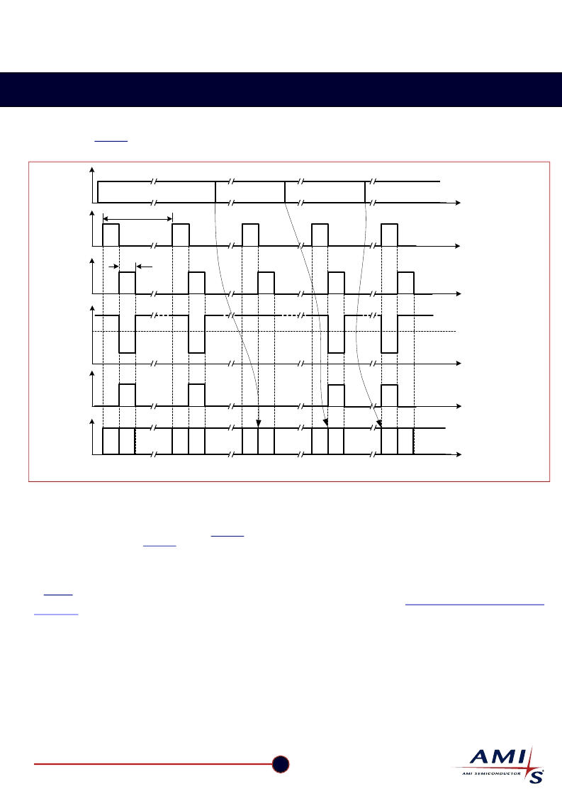
As illustrated in
Table 16
the state is depending on the previous state, the condition of the 2 switch controls (DriveLS and DriveHS) and
the output of HW2_Cmp. Figure 12 is showing an example of a practical case where a connection to VBAT is interrupted.
t
R
th
Tsw = 1024
μ
s
DriveHS
"R"-Comp
t
t
t
DriveLS
HW2_Cmp
State
t
Tsw_on = 128
μ
s
Condition
R2VBAT
OPEN
H
L
F
H
H
H
H
R2VBAT
R2GND
F
H
F
F
H
H
L
L
t
Figure 12: Timing Diagram Showing the Change in States for HW2 Comparator
R2VBAT
A resistor is connected between VBAT and HW2. Every 1024
μ
s S
BOT
is closed a current is sensed, the output of the I
R converter is
low and the HW2_Cmp output is high. Assuming the previous state was floating, the internal LOGIC will interpret this as a change of
state and the new state will be High. (see also
Table 16
). The next time S
BOT
is closed the same conditions are observed. The previous
state was High, so based on
Table 16
the new state remains unchanged. This high state will be interpreted as HW2 address = 1
OPEN
In case the HW2 connection is lost (broken wire, bad contact in connector) the next time S
BOT
is closed this will be sensed. There will be
no current, the output of the corresponding I
R converter is High and the HW2_Cmp will be low. The previous state was High. Based
in
Table 1
6 one can see that the state changes to float. This will trigger a motion to secure position after a debounce time of 64 ms.
This prevents false triggering in case of false micro interruptions of the power supply. See also
Electrical transient conduction along
supply lines
R2GND
If a resistor is connected between HW2 and the GND, a current is sensed every 1024
μ
s whet S
TOP
is closed. The output of the top I
R converter is low and as a result the HW2_Cmp output switches to High. Again based on the stated diagram in Table 1 one can see
that the state will change to Low. This low state will be interpreted as HW2 address = 0.
21
AMI Semiconductor
– June 2006, Rev 3.0
www.amis.com
相關PDF資料 |
PDF描述 |
|---|---|
| AMIS-30623AAGA | LIN Microstepping Motordriver |
| AMIS-30623AANA | LIN Microstepping Motordriver |
| AMIS-30623BAGA | LIN Microstepping Motordriver |
| AMIS-30623BANA | LIN Microstepping Motordriver |
| AMIS-30624 | I2C Microstepping Motordriver |
相關代理商/技術參數(shù) |
參數(shù)描述 |
|---|---|
| AMIS-30623AAGA | 制造商:AMI 制造商全稱:AMI 功能描述:LIN Microstepping Motordriver |
| AMIS-30623AANA | 制造商:AMI 制造商全稱:AMI 功能描述:LIN Microstepping Motordriver |
| AMIS-30623BAGA | 制造商:AMI 制造商全稱:AMI 功能描述:LIN Microstepping Motordriver |
| AMIS-30623BANA | 制造商:AMI 制造商全稱:AMI 功能描述:LIN Microstepping Motordriver |
| AMIS30623C6238G | 功能描述:馬達/運動/點火控制器和驅(qū)動器 LIN STEPPER DRIVER STALL RoHS:否 制造商:STMicroelectronics 產(chǎn)品:Stepper Motor Controllers / Drivers 類型:2 Phase Stepper Motor Driver 工作電源電壓:8 V to 45 V 電源電流:0.5 mA 工作溫度:- 25 C to + 125 C 安裝風格:SMD/SMT 封裝 / 箱體:HTSSOP-28 封裝:Tube |
發(fā)布緊急采購,3分鐘左右您將得到回復。