- 您現(xiàn)在的位置:買賣IC網(wǎng) > PDF目錄1908 > CP82C89 (Intersil)IC ARBITER BUS 5V 8MHZ 20-DIP PDF資料下載
參數(shù)資料
| 型號: | CP82C89 |
| 廠商: | Intersil |
| 文件頁數(shù): | 6/13頁 |
| 文件大?。?/td> | 0K |
| 描述: | IC ARBITER BUS 5V 8MHZ 20-DIP |
| 標(biāo)準(zhǔn)包裝: | 180 |
| 控制器類型: | CMOS 優(yōu)先中斷控制器 |
| 電源電壓: | 4.5 V ~ 5.5 V |
| 電流 - 電源: | 1mA |
| 工作溫度: | 0°C ~ 70°C |
| 安裝類型: | 通孔 |
| 封裝/外殼: | 20-DIP(0.300",7.62mm) |
| 供應(yīng)商設(shè)備封裝: | 20-PDIP |
| 包裝: | 管件 |

2
FN2980.2
February 27, 2006
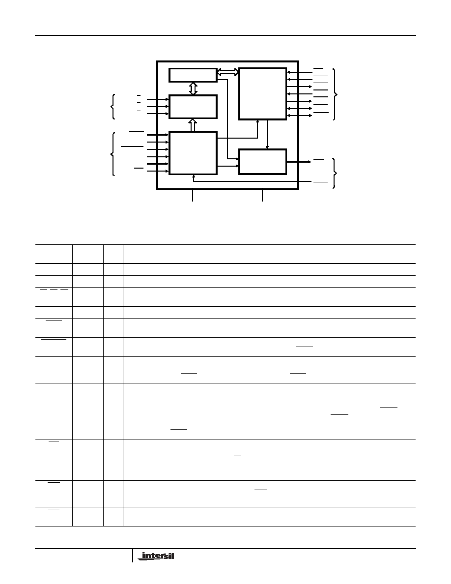
Functional Diagram
Pin Description
PIN
SYMBOL
NUMBER TYPE
DESCRIPTION
VCC
20
VCC: The +5V Power supply pin. A 0.1F capacitor between pins 10 and 20 is recommended for decoupling.
GND
10
GROUND.
S0, S1, S2
1, 18-19
I
STATUS INPUT PINS: The status input pins from an 80C86, 80C88 or 8089 processor. The 82C89 decodes
these pins to initiate bus request and surrender actions. (See Table 1).
CLK
17
I
CLOCK: From the 82C84A or 82C85 clock chip and serves to establish when bus arbiter actions are initiated.
LOCK
16
I
LOCK: A processor generated signal which when activated (low) prevents the arbiter from surrendering the multi-
master system bus to any other bus arbiter, regardless of its priority.
CRQLCK
15
I
COMMON REQUEST LOCK: An active low signal which prevents the arbiter from surrendering the multi-master
system bus to any other bus arbiter requesting the bus through the CBRQ input pin.
RESB
4
I
RESIDENT BUS: A strapping option to configure the arbiter to operate in systems having both a multi-master
system bus and a Resident Bus. Strapped high, the multi-master system bus is requested or surrendered as a
function of the SYSB/RESB input pin. Strapped low, the SYSB/RESB input is ignored.
ANYRQST
14
I
ANY REQUEST: A strapping option which permits the multi-master system bus to be surrendered to a lower
priority arbiter as if it were an arbiter of higher priority (i.e., when a lower priority arbiter requests the use of the
multi-master system bus, the bus is surrendered as soon as it is possible). When ANYRQST is strapped low, the
bus is surrendered according to Table A in Design Information. If ANYRQST is strapped high and CBRQ is
activated, the bus is surrendered at the end of the present bus cycle. Strapping CBRQ low and ANYRQST high
forces the 82C89 arbiter to surrender the multi-master system bus after each transfer cycle. Note that when
surrender occurs BREQ is driven false (high).
IOB
2
I
IO BUS: A strapping option which configures the 82C89 Arbiter to operate in systems having both an IO Bus
(Peripheral Bus) and a multi-master system bus. The arbiter requests and surrenders the use of the multi-master
system bus as a function of the status line, S2. The multi-master system bus is permitted to be surrendered while
the processor is performing IO commands and is requested whenever the processor performs a memory
command. Interrupt cycles are assumed as coming from the peripheral bus and are treated as an IO command.
AEN
13
O
ADDRESS ENABLE: The output of the 82C89 Arbiter to the processor’s address latches, to the 82C88 Bus
Controller and 82C84A or 82C85 Clock Generator. AEN serves to instruct the Bus Controller and address latches
when to three-state their output drivers.
INIT
6
I
INITIALIZE: An active low multi-master system bus input signal used to reset all the bus arbiters on the multi-
master system bus. After initialization, no arbiters have the use of the multi-master system bus.
CONTROL
ARBITRATION
MULTIBUS
INTERFACE
LOCAL
BUS
INTERFACE
+5V
GND
CONTROL/
STRAPPING
OPTIONS
80C86/
80C88
STATUS
COMMAND
SIGNALS
MULTIBUS
SYSTEM
SIGNALS
MULTIBUS is an Intel Corp. trademark.
BPRN
SYSB/
RESB
INIT
BCLK
BREQ
BPRO
BUSY
CBRQ
AEN
CLK
RESB
ANYRQST
LOCK
S 1
IOB
CRQLCK
S 0
S 2
STATUS
DECODER
82C89
相關(guān)PDF資料 |
PDF描述 |
|---|---|
| CPC1465D | IC DC TERMINATION 16-SOIC |
| CPC1465M | IC SHDSL/ISDN DC TERM 16MLP |
| CPC2400E | MODULE MODEM 2400BAUD EMBEDDEDED |
| CPC5601D | IC DRVR PROGRAMMABLE 16-SOIC |
| CPC5710N | IC PHONE LINE MONITOR 8-SOIC |
相關(guān)代理商/技術(shù)參數(shù) |
參數(shù)描述 |
|---|---|
| CP82C89S2064 | 制造商:Rochester Electronics LLC 功能描述:- Bulk |
| CP82C89Z | 功能描述:輸入/輸出控制器接口集成電路 W/ANNEAL PERIPH BUS ARBITER 5V 8MHZ RoHS:否 制造商:Silicon Labs 產(chǎn)品: 輸入/輸出端數(shù)量: 工作電源電壓: 最大工作溫度:+ 85 C 最小工作溫度:- 40 C 安裝風(fēng)格:SMD/SMT 封裝 / 箱體:QFN-64 封裝:Tray |
| CP8300BT | 功能描述:IC MCU 制造商:cypress semiconductor corp 系列:* 零件狀態(tài):最後搶購 標(biāo)準(zhǔn)包裝:1 |
| CP8300BTT | 功能描述:IC MCU 制造商:cypress semiconductor corp 系列:* 零件狀態(tài):最後搶購 標(biāo)準(zhǔn)包裝:1 |
| CP8301AT | 功能描述:IC MCU 制造商:cypress semiconductor corp 系列:* 零件狀態(tài):最後搶購 標(biāo)準(zhǔn)包裝:1 |
發(fā)布緊急采購,3分鐘左右您將得到回復(fù)。