- 您現(xiàn)在的位置:買賣IC網(wǎng) > PDF目錄376597 > DDC118IRTCT Octal Current Input 20-Bit Analog-To-Digital Converter PDF資料下載
參數(shù)資料
| 型號: | DDC118IRTCT |
| 英文描述: | Octal Current Input 20-Bit Analog-To-Digital Converter |
| 中文描述: | 八路電流輸入20位模擬數(shù)字轉(zhuǎn)換器 |
| 文件頁數(shù): | 15/30頁 |
| 文件大?。?/td> | 384K |
| 代理商: | DDC118IRTCT |
第1頁第2頁第3頁第4頁第5頁第6頁第7頁第8頁第9頁第10頁第11頁第12頁第13頁第14頁當(dāng)前第15頁第16頁第17頁第18頁第19頁第20頁第21頁第22頁第23頁第24頁第25頁第26頁第27頁第28頁第29頁第30頁

""#
SBAS325A JUNE 2004 REVISED JUNE 2005
www.ti.com
15
TIMING EXAMPLES
Cont Mode
A few timing diagrams help illustrate the operation of the
state machine. These diagrams are shown in Figure 11
through Figure 19. Table 6 gives generalized timing
specifications in units of CLK periods for CLK_4X = 0. If
CLK_4X = 1, these values increase by a factor of four
because of the internal clock divider. Values (in
μ
s) for
Table 6 can be easily found for a given CLK. For example,
if CLK = 4MHz, then a CLK period = 0.25
μ
s. t
6
in Table 6
would then be 367.50
±
0.125
μ
s.
Table 6. Timing Specifications Generalized in
CLK Periods
SYMBOL
DESCRIPTION
VALUE
(CLK periods with CLK_4X = 0)
1470
±
0.5
1380
±
0.5
1379
±
1
1450
2901
±
1
t6
t7
t8
t9
t10
Cont mode m/r/az cycle
Cont mode data ready
1st ncont mode data ready
2nd ncont mode data ready
Ncont mode m/r/az cycle
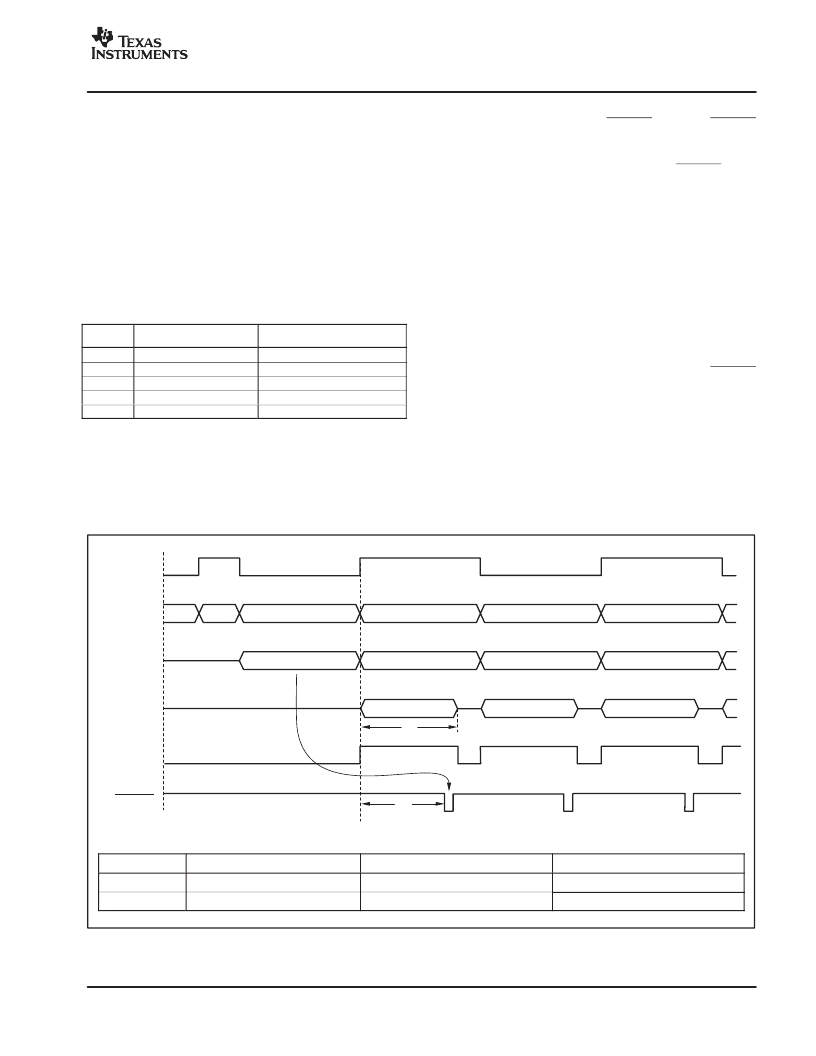
Figure 11 shows a few integration cycles beginning with
initial power-up for a cont mode example. The top signal
is CONV and is supplied by the user. The next line
indicates the current state in the state diagram. The
following two traces show when integrations and
measurement cycles are underway. The internal signal
mbsy is shown next. Finally, DVALID is given. DVALID
goes active low when data is ready to be retrieved from the
DDC118. It stays low until DCLK is taken high and then
back low by the user. The text below the DVALID pulse
indicates the side of the data available to be read, and
arrows help match the data to the corresponding
integration. The signals illustrated in Figure 11 through
Figure 19 are drawn at approximately the same scale.
In Figure 11, the first state is ncont state 8. The DDC118
always powers up in the ncont mode. In this case, the first
state is 8 because CONV is initially low. After the first two
states, cont mode operation is reached and the states
begin toggling between 4 and 5. From now on, the input is
being continuously integrated, either on side A or side B.
The time needed for the m/r/az cycle, or t
6
, is the same time
that determines the boundary between the cont and ncont
modes described earlier in the Overview section. DVALID
goes low after CONV toggles in time t
7
, indicating that data
is ready to be retrieved. As shown in Figure 11, there are
two values for t
6
and t
7
. The reason for this is discussed in
the
Special Considerations
section.
See Figure 12 for the timing diagram of the internal
operations occurring during continuous mode operation.
Table 7 gives the timing specifications in the continuous
mode.
SYMBOL
DESCRIPTION
VALUE (CLK = 4MHz, CLK_4X = 0)
VALUE (CLK = 4.8MHz, CLK_4X = 0)
t6
t7
Cont Mode m/r/az Cycle
367.50
±
0.125
μ
s
345.00
±
0.125
μ
s
306.25
±
0.104
μ
s
287.5
±
0.104
μ
s
Cont Mode Data Ready
Figure 11. Continuous Mode Timing
5
6
7
8
4
5
Integrate A
Integrate B
Integrate B
Integrate A
m/r/az
B
m/r/az
A
m/r/az
B
CONV
State
Integration
Status
m/r/az
Status
mbsy
DVALID
t
6
t
7
t = 0
PowerUp
Side B
Data
Side A
Data
Side B
Data
相關(guān)PDF資料 |
PDF描述 |
|---|---|
| DDG-GJS-K1 | LED GaP |
| DDR-GJS-J2L1-1-I1 | LED GaP |
| DDR-GJS-K1 | LED GaP |
| DDR-GJS-K2 | LED GaP |
| DDR-GJS-L1 | LED GaP |
相關(guān)代理商/技術(shù)參數(shù) |
參數(shù)描述 |
|---|---|
| DDC118IRTCT | 制造商:Texas Instruments 功能描述:IC ADC 20BIT OCTAL 48-VQFN |
| DDC118IRTCT | 制造商:Texas Instruments 功能描述:A/D CONVERTER (A-D) IC ((NW)) |
| DDC118IRTCTG4 | 功能描述:模數(shù)轉(zhuǎn)換器 - ADC Octal Current-Input 20-Bit RoHS:否 制造商:Texas Instruments 通道數(shù)量:2 結(jié)構(gòu):Sigma-Delta 轉(zhuǎn)換速率:125 SPs to 8 KSPs 分辨率:24 bit 輸入類型:Differential 信噪比:107 dB 接口類型:SPI 工作電源電壓:1.7 V to 3.6 V, 2.7 V to 5.25 V 最大工作溫度:+ 85 C 安裝風(fēng)格:SMD/SMT 封裝 / 箱體:VQFN-32 |
| DDC11XEVM-PDK | 功能描述:數(shù)據(jù)轉(zhuǎn)換 IC 開發(fā)工具 DDC11xEVM-PDK Eval Mod RoHS:否 制造商:Texas Instruments 產(chǎn)品:Demonstration Kits 類型:ADC 工具用于評估:ADS130E08 接口類型:SPI 工作電源電壓:- 6 V to + 6 V |
| DDC122LH | 制造商:DIODES 制造商全稱:Diodes Incorporated 功能描述:NPN PRE-BIASED SMALL SIGNAL SOT-563 DUAL SURFACE MOUNT TRANSISTOR |
發(fā)布緊急采購,3分鐘左右您將得到回復(fù)。