- 您現(xiàn)在的位置:買賣IC網(wǎng) > PDF目錄376777 > DM5806 (Electronic Theatre Controls, Inc.) DM5806 DATA MODULE DIGITAL I/O BOARD PDF資料下載
參數(shù)資料
| 型號(hào): | DM5806 |
| 廠商: | Electronic Theatre Controls, Inc. |
| 英文描述: | DM5806 DATA MODULE DIGITAL I/O BOARD |
| 中文描述: | DM5806數(shù)據(jù)模塊數(shù)字I / O板 |
| 文件頁數(shù): | 16/64頁 |
| 文件大小: | 270K |
| 代理商: | DM5806 |
第1頁第2頁第3頁第4頁第5頁第6頁第7頁第8頁第9頁第10頁第11頁第12頁第13頁第14頁第15頁當(dāng)前第16頁第17頁第18頁第19頁第20頁第21頁第22頁第23頁第24頁第25頁第26頁第27頁第28頁第29頁第30頁第31頁第32頁第33頁第34頁第35頁第36頁第37頁第38頁第39頁第40頁第41頁第42頁第43頁第44頁第45頁第46頁第47頁第48頁第49頁第50頁第51頁第52頁第53頁第54頁第55頁第56頁第57頁第58頁第59頁第60頁第61頁第62頁第63頁第64頁

1-4
P3 — Interrupt and Interrupt Channels (Factory Setting: G Connected; Interrupt Channels Disabled)
This header connector, shown in Figure 1-2, lets you connect an interrupt source selected on P4 to an interrupt
channel, IRQ2 through IRQ7. To connect the interrupt source to an interrupt channel, you must install a jumper
across the desired IRQ channel.
2
3
4
5
6
7
G
P3
IRQ
Fig. 1-2 — Interrupt and Interrupt Channel Jumper, P3
INTERRUPT
+5 V
INTERRUPT
REGISTER
INT
SOURCE
CLR
IRQ STATUS
P3
G
CLR
CLK
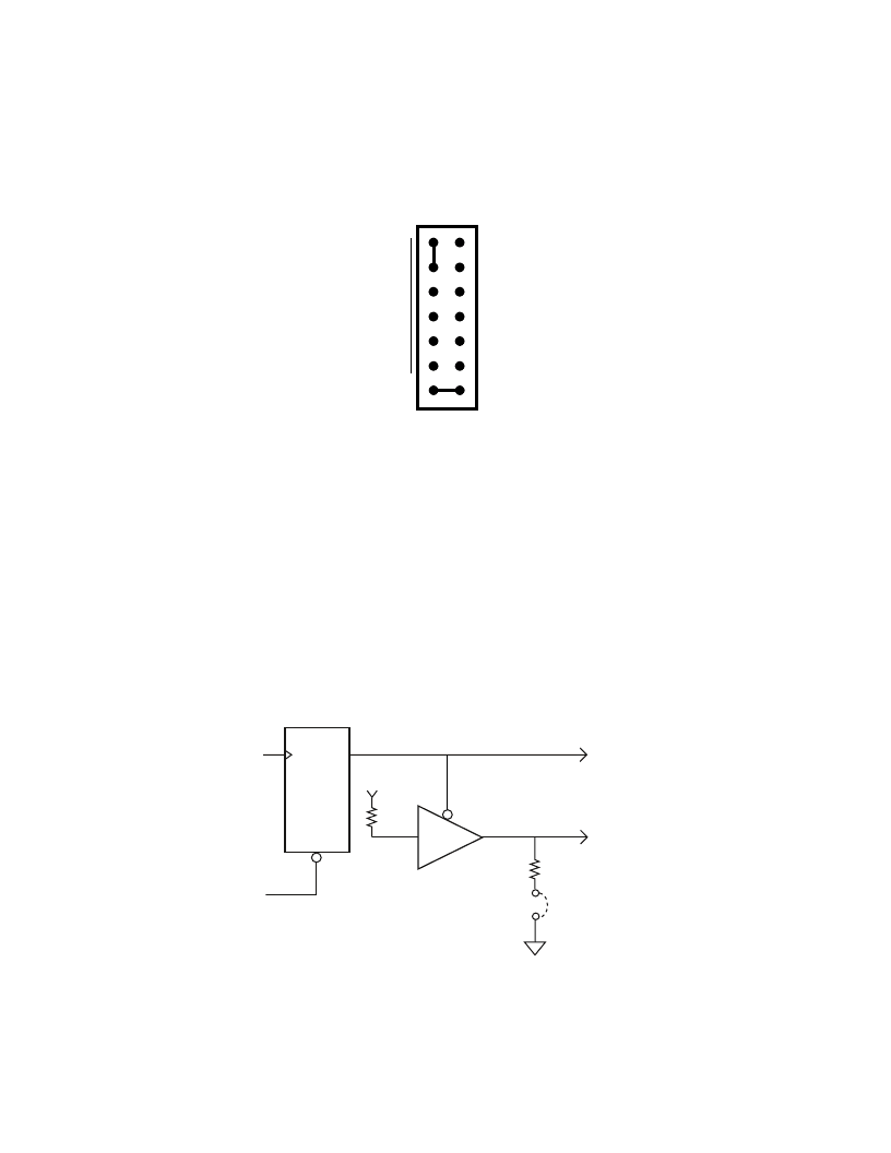
Fig. 1-3 — Pulling Down the Interrupt Request Line
The bottom pair of pins on P3, labeled G, are provided so that you can install a jumper which connects a
1 kilohm pull-down resistor to the output of a high-impedance tri-state driver which carries the interrupt request
signal. This pull-down resistor drives the interrupt request line low whenever interrupts are not active. So, whenever
an interrupt request is made, the tri-state buffer is enabled, forcing the output high and causing an interrupt. You can
monitor the interrupt status through bit 0 in the status word (I/O address location BA + 5). After the interrupt has
been serviced, the clear command returns the IRQ line low, disabling the tri-state buffers, and pulling the output low
again. Figure 1-3 shows this circuit. Because the interrupt request line is driven low only by the pull-down resistor,
you can have two or more boards which share the same IRQ channel. You can tell which board issued the interrupt
request by monitoring each board’s IRQ status bit.
NOTE:
When you use multiple boards that share the same interrupt, only one board should have the G ground
jumper installed. The rest should be disconnected. Whenever you operate a single board, the G jumper should be
installed.
相關(guān)PDF資料 |
PDF描述 |
|---|---|
| DM6806 | DM5806 DATA MODULE DIGITAL I/O BOARD |
| DM6380L | V.34 Integrated Data/ Fax/Voice/Speakerphone Modem Device Set |
| DM6381F | V.34 Integrated Data/ Fax/Voice/Speakerphone Modem Device Set |
| DM6382F | V.34 Integrated Data/ Fax/Voice/Speakerphone Modem Device Set |
| DM6383F | V.34 Integrated Data/ Fax/Voice/Speakerphone Modem Device Set |
相關(guān)代理商/技術(shù)參數(shù) |
參數(shù)描述 |
|---|---|
| DM-59 | 制造商:NTE Electronics 功能描述:DMM W/CAP/FREQ/HFE |
| DM5910J | 制造商:n/a 功能描述:DM 91PF 5% |
| DM5B355J | 制造商:ELP 功能描述:AF535X050 |
| DM5E330J | 制造商:MISCELLANEOUS MANUFACTURERS 功能描述:CAPACITOR MICA |
| DM5EC470J03 | 制造商:MISCELLANEOUS MANUFACTURERS 功能描述:CAPACITOR MICA |
發(fā)布緊急采購,3分鐘左右您將得到回復(fù)。