- 您現(xiàn)在的位置:買賣IC網(wǎng) > PDF目錄68995 > FMS2704LT1C (FAIRCHILD SEMICONDUCTOR CORP) SPECIALTY ANALOG CIRCUIT, PDSO24 PDF資料下載
參數(shù)資料
| 型號(hào): | FMS2704LT1C |
| 廠商: | FAIRCHILD SEMICONDUCTOR CORP |
| 元件分類: | 模擬信號(hào)調(diào)理 |
| 英文描述: | SPECIALTY ANALOG CIRCUIT, PDSO24 |
| 封裝: | TSSOP-24 |
| 文件頁(yè)數(shù): | 11/39頁(yè) |
| 文件大小: | 173K |
| 代理商: | FMS2704LT1C |
第1頁(yè)第2頁(yè)第3頁(yè)第4頁(yè)第5頁(yè)第6頁(yè)第7頁(yè)第8頁(yè)第9頁(yè)第10頁(yè)當(dāng)前第11頁(yè)第12頁(yè)第13頁(yè)第14頁(yè)第15頁(yè)第16頁(yè)第17頁(yè)第18頁(yè)第19頁(yè)第20頁(yè)第21頁(yè)第22頁(yè)第23頁(yè)第24頁(yè)第25頁(yè)第26頁(yè)第27頁(yè)第28頁(yè)第29頁(yè)第30頁(yè)第31頁(yè)第32頁(yè)第33頁(yè)第34頁(yè)第35頁(yè)第36頁(yè)第37頁(yè)第38頁(yè)第39頁(yè)

FMS2704/FMS2704L
PRODUCT SPECIFICATION
REV. 1.01 12/2/99
19
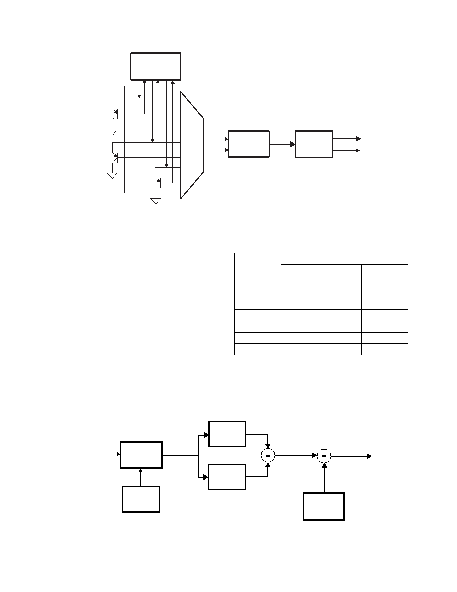
Figure 2. Temperature Processor Block Diagram
Mux
DSP
T7-0
A/D
Converter
Current
Generators
FAULT
Remote
Thermal
Diodes
Local
Thermal
Diode
A differential multiplexer selects the thermal diode input
voltage to be applied to the A/D converter and the bandgap
used for the A/D calibration cycle. Voltage of the diode is
sensed at two currents:10 and 100A. During the diode sam-
pling interval, the A/D converter digitizes low and high cur-
rent samples. DSP averages and subtracts the samples to
output an 8-bit temperature that is updated a rate greater than
1Hz. Remote and Local diode temperatures are outputted
alternately on the T7-0 bus which is connected to the
Temperature Registers.
Remote Diode fault sensing is included within the DSP block.
If either remote diode voltage indicates either a short or an
open circuit, the appropriate FAULT_D1 or FAULT_D2 bit is
set in the Interrupt Status Register.
Temperature data format is 8-bit, two’s complement with the
LSB equivalent to 1.0°C. Range and conversion between °C
and equivalent binary and hexadecimal data is exemplied in
Table 1.
Table 1. Temperature/Data Conversion/Format
A block diagram of the processing shared by the thermometer
channels is shown in Figure 3.
Temperature
Digital Output
Binary
Hex
+125°C
0111 1101
0x7D
+25°C
0001 1001
0x19
+1.0°C
0000 0001
0x01
0°C
0000 0000
0x00
-1.0°C
1111 1111
0xFF
-25°C
1110 0111
0xE7
-55°C
1100 1001
0xC9
Figure 3. Temperature Processor Architecture
A/D
TK[9:0]
TC[8:0]
ADC[13:0]
Sensitivity
Register
(NG)
Offset
Register
(NOS = 272.2)
VHI[13:0]
VLO[13:0]
VPN
Ambient: No A/D averaging
Remote: Average 16 HI/LO sample pairs
相關(guān)PDF資料 |
PDF描述 |
|---|---|
| FMS2704T1C | SPECIALTY ANALOG CIRCUIT, PDSO24 |
| FMS6501MSA28X_NL | 12-CHANNEL, AUDIO/VIDEO SWITCH, PDSO28 |
| FN3000-810-830 | PLL FREQUENCY SYNTHESIZER, DMA37 |
| FNA41060 | AC MOTOR CONTROLLER, DMA26 |
| FNB41560 | AC MOTOR CONTROLLER, DMA26 |
相關(guān)代理商/技術(shù)參數(shù) |
參數(shù)描述 |
|---|---|
| FMS2704MTC | 制造商:Fairchild Semiconductor Corporation 功能描述: |
| FMS2A | 制造商:ROHM Semiconductor 功能描述:100 mA, 40 V, 2 CHANNEL, PNP, Si, SMALL SIGNAL TRANSISTOR |
| FMS2T148 | 制造商:ROHM Semiconductor 功能描述: |
| FMS3 | 制造商:MITA 功能描述:12M COIL SA 38X16MM TRUNK |
| FMS300 | 制造商:Black Box Corporation 功能描述:CAT6 SHIELDED JACK 90 DEGREE |
發(fā)布緊急采購(gòu),3分鐘左右您將得到回復(fù)。