- 您現(xiàn)在的位置:買賣IC網 > PDF目錄68995 > FMS2704LT1C (FAIRCHILD SEMICONDUCTOR CORP) SPECIALTY ANALOG CIRCUIT, PDSO24 PDF資料下載
參數(shù)資料
| 型號: | FMS2704LT1C |
| 廠商: | FAIRCHILD SEMICONDUCTOR CORP |
| 元件分類: | 模擬信號調理 |
| 英文描述: | SPECIALTY ANALOG CIRCUIT, PDSO24 |
| 封裝: | TSSOP-24 |
| 文件頁數(shù): | 27/39頁 |
| 文件大小: | 173K |
| 代理商: | FMS2704LT1C |
第1頁第2頁第3頁第4頁第5頁第6頁第7頁第8頁第9頁第10頁第11頁第12頁第13頁第14頁第15頁第16頁第17頁第18頁第19頁第20頁第21頁第22頁第23頁第24頁第25頁第26頁當前第27頁第28頁第29頁第30頁第31頁第32頁第33頁第34頁第35頁第36頁第37頁第38頁第39頁

FMS2704/FMS2704L
PRODUCT SPECIFICATION
REV. 1.01 12/2/99
33
Notes:
1. Unless stated otherwise, values shown in Typ. column are typical for VCC = 3.3/5.0V and TA = 25°C.
Reset Generators
VRES
Threshold Voltage
FMS2704
4.4
V
FMS2704L
2.9
V
tRES
Reset Interval
200
msec.
System Performance Characteristics (continued)
Parameter
Conditions
Min
Typ1
Max
Unit
Applications Information
Before illustrating some applications with a few examples,
below are several guidelines that should be adopted to opti-
mize performance of the FMS2704.
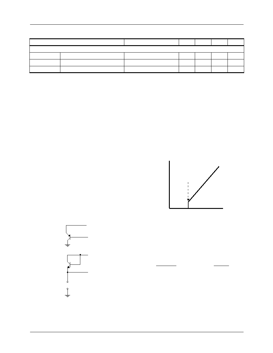
Thermal Diode Connections
When connecting a bipolar transistor congured as a thermal
diode, sensing the base-emitter junction with the collector dis-
connected is not recommended. Intrinsic base resistance will
induce an error causing the indicated temperature to be high.
Instead connect the transistor in either of the congurations
shown in Figure 20:
1.
PNP: Collector connected to ground, with DXP con-
nected to the emitter and DXN connected to the base.
2.
NPN: Collector connected to base, with DXN con-
nected to the emitter and DXP connected to the base.
Within the FMS2704, there is a return to ground through the
DXN pin which conducts the base current of a PNP transistor
or the emitter current from an NPN transistor.
Figure 20. Thermal Diode Connections
Cleanly route the DXP1, DXN1 and DXP2, DXN2 analog
traces as pairs over the ground plane. Segregate DXP2-1,N2-1
traces from digital traces and areas of noise.
Parasitic voltages and leakage can cause errors. Voltage sensi-
tivity is 200V/°C. 1A current leakage can cause a 4%
change in sensitivity that corresponds to a 12°C error at room
temperature.
Fan Control
Whether setting the fan speed through the SMBus or using the
internal controller, the fan speed should be constrained
between a value corresponding to stall speed and normal rated
speed. Stall speed is typically 30% of normal speed.
Figure 21. Fan Speed verses Drive Voltage
General
Power is supplied to the VCCA and VCCD pins, which should
be de-coupled to ground through local 0.1F chip capacitors.
To minimize the effects of noise, locate the FMS2704 over a
ground plane.
Input pin STANDBY and bi-directional pin THERM, should
be biased to VCCD through a pull-up resistor to prevent spuri-
ous triggering. Tachometer inputs are internally biased to
VCCD.
Serial Bus pins SCL and SDA require pull-up resistors along
the bus but not necessarily local to the FMS2704. ADD must
be set H, L or open to match the FMS2704 address to the
assigned Serial Bus address.
DX P
DX N
DXP
DX N
Q1
PNP
Q2
NPN
JP1
Opitional Ground
F
a
n
S
p
e
d
(R
P
M
)
Voltage
Stall Voltage
相關PDF資料 |
PDF描述 |
|---|---|
| FMS2704T1C | SPECIALTY ANALOG CIRCUIT, PDSO24 |
| FMS6501MSA28X_NL | 12-CHANNEL, AUDIO/VIDEO SWITCH, PDSO28 |
| FN3000-810-830 | PLL FREQUENCY SYNTHESIZER, DMA37 |
| FNA41060 | AC MOTOR CONTROLLER, DMA26 |
| FNB41560 | AC MOTOR CONTROLLER, DMA26 |
相關代理商/技術參數(shù) |
參數(shù)描述 |
|---|---|
| FMS2704MTC | 制造商:Fairchild Semiconductor Corporation 功能描述: |
| FMS2A | 制造商:ROHM Semiconductor 功能描述:100 mA, 40 V, 2 CHANNEL, PNP, Si, SMALL SIGNAL TRANSISTOR |
| FMS2T148 | 制造商:ROHM Semiconductor 功能描述: |
| FMS3 | 制造商:MITA 功能描述:12M COIL SA 38X16MM TRUNK |
| FMS300 | 制造商:Black Box Corporation 功能描述:CAT6 SHIELDED JACK 90 DEGREE |
發(fā)布緊急采購,3分鐘左右您將得到回復。