- 您現(xiàn)在的位置:買賣IC網(wǎng) > PDF目錄384399 > HE85750 (King Billion Electronics Co., Ltd.) 8-bit Micro-controller PDF資料下載
參數(shù)資料
| 型號(hào): | HE85750 |
| 廠商: | King Billion Electronics Co., Ltd. |
| 英文描述: | 8-bit Micro-controller |
| 中文描述: | 8位微控制器 |
| 文件頁(yè)數(shù): | 3/23頁(yè) |
| 文件大小: | 399K |
| 代理商: | HE85750 |
第1頁(yè)第2頁(yè)當(dāng)前第3頁(yè)第4頁(yè)第5頁(yè)第6頁(yè)第7頁(yè)第8頁(yè)第9頁(yè)第10頁(yè)第11頁(yè)第12頁(yè)第13頁(yè)第14頁(yè)第15頁(yè)第16頁(yè)第17頁(yè)第18頁(yè)第19頁(yè)第20頁(yè)第21頁(yè)第22頁(yè)第23頁(yè)
King Billion Electronics Co., Ltd
駿
億
電
子
股
份
有
限
公
司
HE85750
HE80000 SERIES
2003/7/30
This specification is subject to change without notice. Please contact sales person for the latest version before use.
3
V1.52E
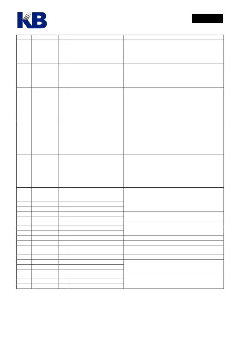
Pin No
Pin Name
I/O
Function
Description
34..
37
PRTC[7:4]
B 4-pin bi-directional I/O port.
Mask options
:
MO_CPP[7..5]=1 ~ Push-pull.
=0 ~ Open-drain.
Output must be “1” before reading whenever uses them as
input (No tri-state structure).
Mask options
:
MO_DPP[7..0]=1 ~ Push-pull.
=0 ~ Open-drain.
Output must be “1” before reading whenever uses them as
input (No tri-state structure).
Mask options
:
MO_LIO14[7..0]=1 ~ LCD Pin.
=0 ~ I/O Pin.
MO_14PP[7..0]=1 ~ Push-pull.
=0 ~ Open-drain.
Output must be “1” before reading whenever uses them as
input (No tri-state structure).
Mask options
:
MO_LIO15[7..0]=1 ~ LCD Pin.
=0 ~ I/O Pin.
MO_15PP[7..0]=1 ~ Push-pull.
=0 ~ Open-drain.
Output must be “1” before reading whenever uses them as
input (No tri-state structure).
Mask options
:
MO_LIO17[7..0]=1 ~ LCD Pin.
=0 ~ I/O Pin.
MO_17PP[7..0]=1 ~ Push-pull.
=0 ~ Open-drain.
Output must be “1” before reading whenever uses them as
input (No tri-state structure).
24..
31
PRTD[7:0]
B
8-pin bi-directional I/O port.
PRTD[7..2] as wake-up pin.
PRTD[7..6] as external interrupt
pin.
94..
101
PRT14[7:0]/
SEG[23:16]
B/
O
8-pin bi-directional I/O port that
is shared with LCD segment pin.
102..
109
PRT15[7:0]/
SEG[15:8]
B/
O
8-pin bi-directional I/O port that
is shared with LCD segment pin.
110..
117
PRT17[7:0]/
SEG[7:0]
B/
O
8-pin bi-directional I/O port that
is shared with LCD segment pin.
53..38
118..
133
69..54
CMSG[47:32]
O COM[47:32] / SEG[48:63]
70..93
SEG[47:24]
O LCD SEGMENT Output
2
LC2
B Charge Pump Switch 1
1
LC1
B Charge Pump Switch 2
5
L V3
B Charge Pump V3
4
L V2
B Charge Pump V2
3
L V1
B Charge Pump V1
6..10
LR[4..0]
B LCD Resister level 4 ~ 1
11
L VG
I
COM[31:0]
O LCD COMMON Output
LCD Data filled from
PAGE 6 and 7
, please refer the LCD
RAM map.
Add one 0.1 μF capacitor between LC1 and LC2. Please
refer the application circuit.
LV3< 8.5 Volts.
Please refer the application circuit.
Please refer the application circuit.
Please refer the application circuit.
LCD Virtual Ground
The PWM positive output can
drive speaker or buzzer directly.
O D/A output.
I
DAC Voice Output
I
OPAMP negative input pin.
O OPAMP positive input pin.
P OPAMP output pin.
P Power Ground Input
P Dedicated PWM Ground
33
PWM
O
Set the bit2 of VOC register as one to turn on PWM.
13
14
15
16
23
12
32
VO
OPIN
OPIP
OPO
VDD
GND
Bit 1 of VOC = ‘1’ , Turn on DA
Set the VOC[1] (DA=1) to turn on DAC with VO output.
Built-in OP comparator. Set the VOC[0] = ‘1’ , Turn on OP
GND_PWM
All of power must connect to power source, can not be
floating.
相關(guān)PDF資料 |
PDF描述 |
|---|---|
| HE89410 | 8-BIT MICRO-CONTROLLER |
| HE89810 | 8-BIT MICRO-CONTROLLER |
| HE89820 | 8-BIT MICRO-CONTROLLER |
| HE89A20 | 8-BIT MICRO-CONTROLLER |
| HE89A21 | 8-BIT MICRO-CONTROLLER |
相關(guān)代理商/技術(shù)參數(shù) |
參數(shù)描述 |
|---|---|
| HE85750(S) | 制造商:未知廠家 制造商全稱:未知廠家 功能描述: |
| HE861 | 制造商:BOWEI 制造商全稱:BOWEI 功能描述:Broadband Amplifier |
| HE863AUD102T007 | 制造商:Telit 功能描述: |
| HE863EUD102T016 | 制造商:Telit 功能描述: |
| HE863EUR102T007 | 制造商:Telit 功能描述: |
發(fā)布緊急采購(gòu),3分鐘左右您將得到回復(fù)。