- 您現(xiàn)在的位置:買賣IC網(wǎng) > PDF目錄370686 > HS9-82C37ARH-8 (Harris Corporation) Radiation Hardened CMOS High Performance Programmable DMA Controller PDF資料下載
參數(shù)資料
| 型號: | HS9-82C37ARH-8 |
| 廠商: | Harris Corporation |
| 英文描述: | Radiation Hardened CMOS High Performance Programmable DMA Controller |
| 中文描述: | 輻射加固的CMOS高性能可編程DMA控制器 |
| 文件頁數(shù): | 23/28頁 |
| 文件大小: | 253K |
| 代理商: | HS9-82C37ARH-8 |
第1頁第2頁第3頁第4頁第5頁第6頁第7頁第8頁第9頁第10頁第11頁第12頁第13頁第14頁第15頁第16頁第17頁第18頁第19頁第20頁第21頁第22頁當(dāng)前第23頁第24頁第25頁第26頁第27頁第28頁

23
HS-82C37ARH
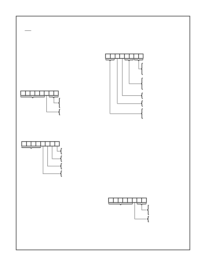
Mask Register
- Each channel has associated with it a
mask bit which can be set to disable an incoming DREQ.
Each mask bit is set when its associated channel produces
an EOP if the channel is not programmed to Autoinitialize.
Each bit of the 4-bit Mask Register may also be set or
cleared separately or simultaneously under soft-ware con-
trol. The entire register is also set by a Reset or Master
Clear. This disables all hardware DMA requests until a clear
Mask Register instruction allows them to occur. The instruc-
tion to separately set or clear the mask bits is similar in form
to that used with the Request Register. Refer to the following
table and Figure 10 for details. When reading the Mask Reg-
ister, bits 4-7 will always read as logical ones, and bits 0-3
will display the mask bits of channel 0-3, respectively. The 4
bits of the Mask Register may be cleared simultaneously by
using the Clear Mask Register command (see software com-
mands section).
Mask Register
All four bits of the Mask Register may also be written with a
single command.
7
6
5
4
3
2
1
0
00
01
10
11
0
1
BIT NUMBER
SELECT CHANNEL 0 MASK BIT
SELECT CHANNEL 1 MASK BIT
SELECT CHANNEL 2 MASK BIT
SELECT CHANNEL 3 MASK BIT
CLEAR MASK BIT
SET MASK BIT
DON’T CARE
7
6
5
4
3
2
1
0
0
1
0
1
0
1
BIT NUMBER
CLEAR CHANNEL 0 MASK BIT
SET CHANNEL 0 MASK BIT
CLEAR CHANNEL 1 MASK BIT
SET CHANNEL 1 MASK BIT
CLEAR CHANNEL 2 MASK BIT
SET CHANNEL 2 MASK BIT
DON’T CARE,
WRITE ALL
ONES,
READ
0
1
CLEAR CHANNEL 3 MASK BIT
SET CHANNEL 3 MASK BIT
Mode Register
- Each channel has a 6-bit Mode Register
associated with it. When the register is being written to by
the microprocessor in the Program Condition, bits 0 and 1
determine which channel Mode Register is to be written.
When the processor reads a Mode Register, bits 0 and 1 will
both be ones. See the adjacent table and Figure 10 for Mode
Register functions and addresses.
Mode Register
Request Register
- The HS-82C37ARH can respond to
requests for DMA service which are initiated by software as
well as by a DREQ. Each channel has a request bit associ-
ated with it in the 4-bit Request Register. These are non-
maskable and subject to prioritization by the Priority Encoder
network. Each register bit is set or reset separately under
software control. The entire register is cleared by a Reset. To
set or reset a bit, the software loads the proper form of the
data word. See Figure 10 for register address coding, and
the following table for Request Register format. A software
request for DMA operation can be made in Block or Single
Modes. For Memory-to-Memory transfers, the software
request for channel 0 should be set. When reading the
Request Register, bits 4-7 will always read as ones, and bits
0-3 will display the request bits of channels 0-3 respectively.
Request Register
7
6
5
4
3
2
1
0
00
01
10
11
XX
READBACK
BIT NUMBER
CHANNEL 0 SELECT
CHANNEL 1 SELECTT
CHANNEL 2 SELECT
00
01
10
11
XX
IF BITS 6 AND 7 = 11
VERIFY TRANSFER
WRITE TRANSFER
READ TRANSFER
0
1
AUTOINITIALIZATION DISABLE
AUTOINITIALIZATION ENABLE
00
01
10
11
DEMAND MODE SELECT
SINGLE MODE SELECT
BLOCK MODE SELECT
CASCADE MODE SELECT
0
1
ADDRESS INCREMENT SELECT
ADDRESS DECREMENT SELECT
7
6
5
4
3
2
1
0
00
01
10
11
0
1
BIT NUMBER
SELECT CHANNEL 0
SELECT CHANNEL 1
SELECT CHANNEL 2
SELECT CHANNEL 3
RESET REQUEST BIT
SET REQUEST BIT
DON’T CARE,
WRITE BITS 4-7
ALL ONES, READ
Spec Number
518058
相關(guān)PDF資料 |
PDF描述 |
|---|---|
| HS1-82C37ARH-Q | Radiation Hardened CMOS High Performance Programmable DMA Controller |
| HS-82C12 | Radiation Hardened 8-Bit Input/Output Port |
| HS-82C12RH | Radiation Hardened 8-Bit Input/Output Port |
| HS1-82C37ARH | Radiation Hardened CMOS High Performance Programmable DMA Controller |
| HS9-82C37ARH-Q | Radiation Hardened CMOS High Performance Programmable DMA Controller |
相關(guān)代理商/技術(shù)參數(shù) |
參數(shù)描述 |
|---|---|
| HS9-82C37ARH-Q | 制造商:HARRIS 制造商全稱:HARRIS 功能描述:Radiation Hardened CMOS High Performance Programmable DMA Controller |
| HS9-82C54RH | 制造商:INTERSIL 制造商全稱:Intersil Corporation 功能描述:Radiation Hardened CMOS Programmable Interval Timer |
| HS9-82C54RH-8 | 制造商:Intersil Corporation 功能描述:PROGRAMMABLE TIMER SGL 24PIN CFLATPACK - Bulk |
| HS9-82C54RH-Q | 制造商:Intersil Corporation 功能描述:PROGRAMMABLE TIMER SGL 24CFPAK - Bulk |
| HS9-82C85RH | 制造商:INTERSIL 制造商全稱:Intersil Corporation 功能描述:Radiation Hardened CMOS Static Clock Controller/Generator |
發(fā)布緊急采購,3分鐘左右您將得到回復(fù)。