- 您現(xiàn)在的位置:買賣IC網(wǎng) > PDF目錄360744 > ICS2002 Wavedec Digital Audio Codec PDF資料下載
參數(shù)資料
| 型號: | ICS2002 |
| 元件分類: | Codec |
| 英文描述: | Wavedec Digital Audio Codec |
| 中文描述: | Wavedec數(shù)字音頻編解碼器 |
| 文件頁數(shù): | 9/21頁 |
| 文件大小: | 550K |
| 代理商: | ICS2002 |
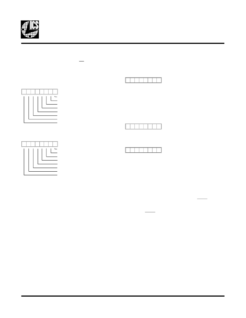
7 6 5 4 3 2 1 0
Clear Play IRQ
Clear Record IRQ
reserved
Power-Down Mode IRQ
FIFO Overflow/Underflow IRQ
Sample Rate IRQ
FIFO Ready
IRQ (same as pin)
Status (Base + 0 read)
7 6 5 4 3 2 1 0
Clear PLAY IRQ
Clear REC IRQ
reserved
Clear PDM IRQ
Clear FOU IRQ
Clear SR IRQ
reserved
reserved
IRQ Reset (Base + 0 write)
This register provides the driver software easy access to the
interrupt source when read. Note that bit 7 indicates the state
of the IRQ pin, and hence will be zero when the MIE bit is zero
(see “Interrupt Enable” register).
A write to the register is performed to clear interrupts. Writing
a one to a given bit will cause the associated interrupt to be
cleared. To release the clear interrupt bit and allow further
interrupts to occur, a zero must be written back to the bit of
interest (some bits have alternate methods of clearing described
later). This feature ensures that if the interrupt condition still
exists, an edge will be generated on the IRQ pin, thus ensuring
recognition on platforms that are edge sensitive. This also
allows for a return from interrupt instruction to be executed on
the platform while the IRQ line is inactive.
Bit 6 is a special case. There is no IRQ associated with this bit.
It is located here for use in Sound Source Emulation Mode, and
represents the BUSY status of a Sound Source. When the
STATUS is read and tested with 40h, a zero result indicates that
the play FIFO is full.
7 6 5 4 3 2 1 0
Register Address (RA) (Base + 1)
7 6 5 4 3 2 1 0
Data Low Byte/Word (DLW)
7 6 5 4 3 2 1 0
Data High Byte (DH) (Base + 3)
Note that this register can only be read in STAND ALONE
mode. Hence, indirect access to this register has been provided
at RA=83h for use in COMPANION mode.
Direct Register Descriptions
The base address is determined externally by an address de-
coder which selects the chip via the CS input.
This register is the indirect pointer to direct data transfers to
and from the data registers. It is a read/write register. Note that
this register can only be read if the chip is in STAND ALONE
mode.
These two addresses are used to accomplish all internal register
reading and writing. Most internal registers are 8-bit or less.
These are accessed by first writing the appropriate value to the
DW, then writing (reading) the data byte to (from) DLW.
I/O Mode FIFO data (RA=0Bh), Algorithm RAM, and Coeffi-
cient RAM are always treated as 16-bit entities, and can be
transferred in two ways:
- a single operation to/from DLW with SBHE = 0
- two successive operations, low byte to/from DLW
with SBHE = 1, then high byte to/from DH.
ICS2002
9
相關(guān)PDF資料 |
PDF描述 |
|---|---|
| ICS2002Y | Wavedec Digital Audio Codec |
| ICS2008B | SMPTE Time Code Receiver/Generator |
| ICS200 | SMPTE Time Code Receiver/Generator |
| ICS2008BEP | SMPTE Time Code Receiver/Generator |
| ICS2008BY-10 | ER 35C 35#16 PIN PLUG |
相關(guān)代理商/技術(shù)參數(shù) |
參數(shù)描述 |
|---|---|
| ICS2002V | 制造商:未知廠家 制造商全稱:未知廠家 功能描述:Soundcard Circuits |
| ICS2002Y | 制造商:ICS 制造商全稱:ICS 功能描述:Wavedec Digital Audio Codec |
| ICS2008AV | 制造商:未知廠家 制造商全稱:未知廠家 功能描述: |
| ICS2008AY | 制造商:未知廠家 制造商全稱:未知廠家 功能描述:Industrial Control IC |
| ICS2008B | 制造商:IDT 制造商全稱:Integrated Device Technology 功能描述:SMPTE Time Code Receiver/Generator |
發(fā)布緊急采購,3分鐘左右您將得到回復(fù)。