- 您現(xiàn)在的位置:買賣IC網(wǎng) > PDF目錄377487 > IDT82V1068 (Integrated Device Technology, Inc.) OCTAL PROGRAMMABLE PCM CODEC PDF資料下載
參數(shù)資料
| 型號: | IDT82V1068 |
| 廠商: | Integrated Device Technology, Inc. |
| 元件分類: | Codec |
| 英文描述: | OCTAL PROGRAMMABLE PCM CODEC |
| 中文描述: | 八路可編程PCM編解碼器 |
| 文件頁數(shù): | 42/375頁 |
| 文件大小: | 2430K |
| 代理商: | IDT82V1068 |
第1頁第2頁第3頁第4頁第5頁第6頁第7頁第8頁第9頁第10頁第11頁第12頁第13頁第14頁第15頁第16頁第17頁第18頁第19頁第20頁第21頁第22頁第23頁第24頁第25頁第26頁第27頁第28頁第29頁第30頁第31頁第32頁第33頁第34頁第35頁第36頁第37頁第38頁第39頁第40頁第41頁當(dāng)前第42頁第43頁第44頁第45頁第46頁第47頁第48頁第49頁第50頁第51頁第52頁第53頁第54頁第55頁第56頁第57頁第58頁第59頁第60頁第61頁第62頁第63頁第64頁第65頁第66頁第67頁第68頁第69頁第70頁第71頁第72頁第73頁第74頁第75頁第76頁第77頁第78頁第79頁第80頁第81頁第82頁第83頁第84頁第85頁第86頁第87頁第88頁第89頁第90頁第91頁第92頁第93頁第94頁第95頁第96頁第97頁第98頁第99頁第100頁第101頁第102頁第103頁第104頁第105頁第106頁第107頁第108頁第109頁第110頁第111頁第112頁第113頁第114頁第115頁第116頁第117頁第118頁第119頁第120頁第121頁第122頁第123頁第124頁第125頁第126頁第127頁第128頁第129頁第130頁第131頁第132頁第133頁第134頁第135頁第136頁第137頁第138頁第139頁第140頁第141頁第142頁第143頁第144頁第145頁第146頁第147頁第148頁第149頁第150頁第151頁第152頁第153頁第154頁第155頁第156頁第157頁第158頁第159頁第160頁第161頁第162頁第163頁第164頁第165頁第166頁第167頁第168頁第169頁第170頁第171頁第172頁第173頁第174頁第175頁第176頁第177頁第178頁第179頁第180頁第181頁第182頁第183頁第184頁第185頁第186頁第187頁第188頁第189頁第190頁第191頁第192頁第193頁第194頁第195頁第196頁第197頁第198頁第199頁第200頁第201頁第202頁第203頁第204頁第205頁第206頁第207頁第208頁第209頁第210頁第211頁第212頁第213頁第214頁第215頁第216頁第217頁第218頁第219頁第220頁第221頁第222頁第223頁第224頁第225頁第226頁第227頁第228頁第229頁第230頁第231頁第232頁第233頁第234頁第235頁第236頁第237頁第238頁第239頁第240頁第241頁第242頁第243頁第244頁第245頁第246頁第247頁第248頁第249頁第250頁第251頁第252頁第253頁第254頁第255頁第256頁第257頁第258頁第259頁第260頁第261頁第262頁第263頁第264頁第265頁第266頁第267頁第268頁第269頁第270頁第271頁第272頁第273頁第274頁第275頁第276頁第277頁第278頁第279頁第280頁第281頁第282頁第283頁第284頁第285頁第286頁第287頁第288頁第289頁第290頁第291頁第292頁第293頁第294頁第295頁第296頁第297頁第298頁第299頁第300頁第301頁第302頁第303頁第304頁第305頁第306頁第307頁第308頁第309頁第310頁第311頁第312頁第313頁第314頁第315頁第316頁第317頁第318頁第319頁第320頁第321頁第322頁第323頁第324頁第325頁第326頁第327頁第328頁第329頁第330頁第331頁第332頁第333頁第334頁第335頁第336頁第337頁第338頁第339頁第340頁第341頁第342頁第343頁第344頁第345頁第346頁第347頁第348頁第349頁第350頁第351頁第352頁第353頁第354頁第355頁第356頁第357頁第358頁第359頁第360頁第361頁第362頁第363頁第364頁第365頁第366頁第367頁第368頁第369頁第370頁第371頁第372頁第373頁第374頁第375頁
IDT82P2281
SINGLE T1/E1/J1 LONG HAUL / SHORT HAUL TRANSCEIVER
Functional Description
31
October 7, 2003
3.8.2.1.2
CRC Multi-Frame
The CRC Multi-Frame is provided to enhance the ability of verifying
the data stream. The structure of TS0 of the CRC Multi-Frame is illus-
trated in Table 18.
A CRC Multi-Frame consists of 16 continuous Basic Frames (No. 0
– 15) which are numbered from a Basic Frame with FAS. Each CRC
Multi-Frame can be divided into two Sub Multi-Frames (SMF I & SMF II).
The first bit of TS0 of each frame is called the International (Si) bit.
The Si bit in each even frame is the CRC bit. Thus, there are C1, C2,
C3, C4 in each SMF. The C1 is the most significant bit, while the C4 is
the least significant bit. The Si bit in the first six odd frames is the CRC
Multi-Frame alignment pattern. Its pattern is ‘001011’. The Si bit in
Frame 13 and Frame 15 are E1 and E2 bits. The value of the E bits can
indicate the Far End Block Errors (FEBE).
After the Basic Frame has been synchronized, the Frame Proces-
sor initiates an 8 and a 400 ms timer to check the CRC Multi-Frame
alignment signal if the CRCEN bit is ‘1’. The CRC Multi-Frame synchro-
nization is declared with a ‘0’ in the OOCMFV bit only if at least two CRC
Multi-Frame alignment patterns are found within 8 ms, with the interval
time of each pattern being a multiple of 2 ms. Then if the received CRC
Multi-Frame alignment signal does not meet its pattern, it will be indi-
cated by the CMFERI bit.
If the 2 CRC Multi-Frame alignment patterns can not be found
within 8ms with the interval time being a multiple of 2 ms, an offline
search for the Basic Frame alignment pattern will start which is indicated
in the OOOFV bit. The process is the same as shown in Figure 10. This
offline operation searches in parallel with the pre-found Basic Frame
synchronization searching process. After the new Basic Frame synchro-
nization is found by this offline search, the 8 ms timer is restarted to
check whether the two CRC Multi-Frame alignment patterns are found
within 8 ms, with the interval time of each pattern being a multiple of 2
ms again. If the condition can not be met, the procedure will go on until
the 400 ms timer ends. If the condition still can not be met at that time
and the Basic Frame is still synchronized, the device declares by the
C2NCIWV bit to run under the CRC to non-CRC interworking process. In
this process, the CRC Multi-Frame alignment pattern can still be
searched if the C2NCIWCK bit is logic 1.
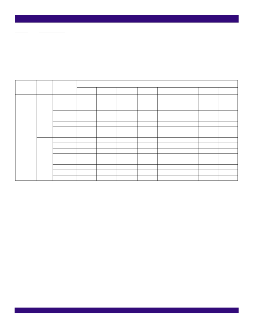
Table 18: The Structure Of TS0 In CRC Multi-Frame
SMF
Basic Frame
No. / Type
the Eight Bits in Timeslot 0
1 (Si bit)
2
3
4
5
6
7
8
CRC-4
Multi-Frame
SMF I
0 / FAS
1 / NFAS
2 / FAS
3 / NFAS
4 / FAS
5 / NFAS
6 / FAS
7 / NFAS
8 / FAS
9 / NFAS
10 / FAS
11 / NFAS
12 / FAS
13 / NFAS
14 / FAS
15 / NFAS
C1
0
C2
0
C3
1
C4
0
C1
1
C2
1
C3
E1
C4
E2
0
1
0
1
0
1
0
1
0
1
0
1
0
1
0
1
0
A
0
A
0
A
0
A
0
A
0
A
0
A
0
A
1
1
0
1
1
Sa4
1
Sa4
1
Sa4
1
Sa4
1
Sa4
1
Sa4
1
Sa4
1
Sa4
Sa5
1
Sa5
1
Sa5
1
Sa5
1
Sa5
1
Sa5
1
Sa5
1
Sa5
Sa6
0
Sa6
0
Sa6
0
Sa6
0
Sa6
0
Sa6
0
Sa6
0
Sa6
Sa7
1
Sa7
1
Sa7
1
Sa7
1
Sa7
1
Sa7
1
Sa7
1
Sa7
Sa8
1
Sa8
1
Sa8
1
Sa8
1
Sa8
1
Sa8
1
Sa8
1
Sa8
SMF II
相關(guān)PDF資料 |
PDF描述 |
|---|---|
| IDT82V1068PF | TTL |
| IDT82V2088 | OCTAL CHANNEL T1/E1/J1 LONG HAUL/ SHORT HAUL LINE INTERFACE UNIT |
| IDT82V3011PV | T1/E1/OC3 WAN PLL WITH SINGLE REFERENCE INPUT |
| IDT82V3012 | T1/E1/OC3 WAN PLL WITH DUAL REFERENCE INPUTS |
| IDT82V3012PV | T1/E1/OC3 WAN PLL WITH DUAL REFERENCE INPUTS |
相關(guān)代理商/技術(shù)參數(shù) |
參數(shù)描述 |
|---|---|
| IDT82V1068PF | 制造商:IDT 制造商全稱:Integrated Device Technology 功能描述:OCTAL PROGRAMMABLE PCM CODEC |
| IDT82V1074 | 制造商:IDT 制造商全稱:Integrated Device Technology 功能描述:CHIPSET OF RINGING SUBSCRIBER LINE INTERFACE CIRCUIT (RSLIC) & QUAD PROGRAMMABLE PCM CODEC |
| IDT82V1074PF | 制造商:IDT 制造商全稱:Integrated Device Technology 功能描述:CHIPSET OF RINGING SUBSCRIBER LINE INTERFACE CIRCUIT (RSLIC) & QUAD PROGRAMMABLE PCM CODEC |
| IDT82V1671 | 制造商:IDT 制造商全稱:Integrated Device Technology 功能描述:CHIPSET OF RINGING SUBSCRIBER LINE INTERFACE CIRCUIT (RSLIC) & QUAD PROGRAMMABLE PCM CODEC |
| IDT82V1671J | 制造商:IDT 制造商全稱:Integrated Device Technology 功能描述:CHIPSET OF RINGING SUBSCRIBER LINE INTERFACE CIRCUIT (RSLIC) & QUAD PROGRAMMABLE PCM CODEC |
發(fā)布緊急采購,3分鐘左右您將得到回復(fù)。