- 您現(xiàn)在的位置:買賣IC網(wǎng) > PDF目錄377500 > IR3651SPBF (International Rectifier) HIGH VOLTAGE SYNCHRONOUS PWM BUCK CONTROLLER PDF資料下載
參數(shù)資料
| 型號(hào): | IR3651SPBF |
| 廠商: | International Rectifier |
| 英文描述: | HIGH VOLTAGE SYNCHRONOUS PWM BUCK CONTROLLER |
| 中文描述: | 高壓同步PWM降壓控制器 |
| 文件頁數(shù): | 13/19頁 |
| 文件大小: | 397K |
| 代理商: | IR3651SPBF |

IR3651SP
b
F
10/11/2006
Input Capacitor Selection
The input filter capacitor should be selected
based on how much ripple the supply can
tolerate on the DC input line. The ripple current
generated during the on time of upper MOSFET
should be provided by input capacitor. The RMS
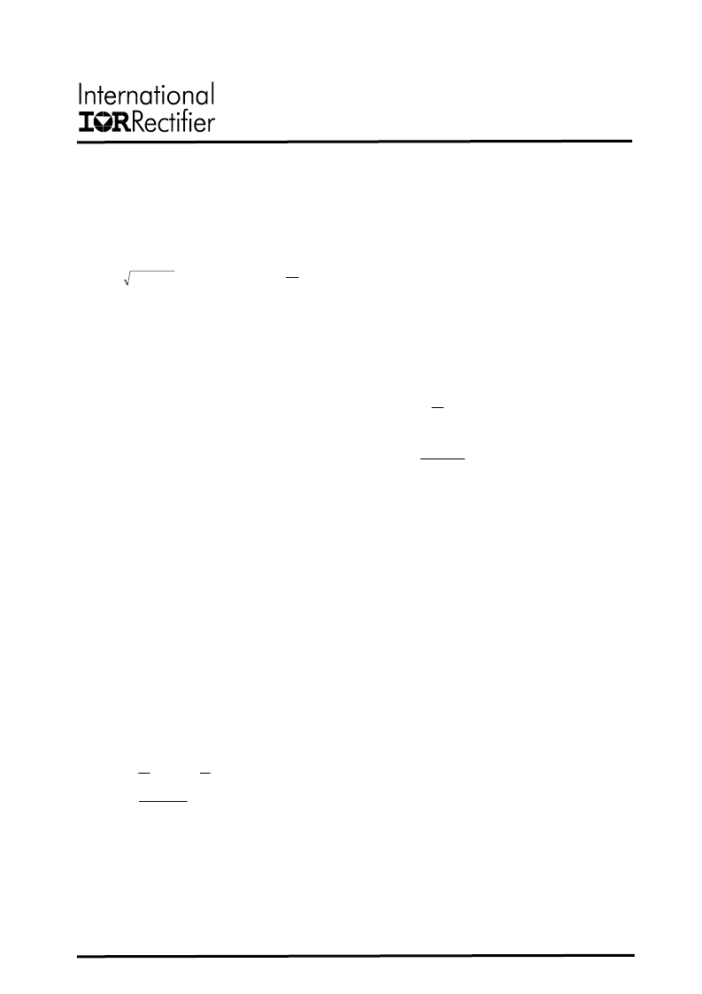
value of this ripple is expressed by:
Where:
D is the Duty Cycle
I
RMS
is the RMS value of the input capacitor
current.
Io is the output current.
For applications with input supplies above 30V,
choice of input capacitor type is limited to
ceramics or aluminum electrolytics. Ceramic
capacitors offer high peak current capabilities,
they also feature low ESR and ESL at higher
frequency which enhance better efficiency,
however high voltage ceramic capacitors are
available with only in low value capacitance. A
combination
of
ceramic
electrolytic capacitors are recommended.
capacitors
and
Inductor Selection
The inductor is selected based on output power,
operating frequency and efficiency requirements.
Low inductor value causes large ripple current,
resulting in the smaller size, faster response to a
load transient but poor efficiency and high output
noise. Generally, the selection of inductor value
can be reduced to desired maximum ripple
current in the inductor . The optimum point is
usually found between 20% and 50% ripple of
the output current.
For the buck converter, the inductor value for
desired
operating
ripple
determined using the following relation:
1
D
t
t
(
)
--(
F
i
V
s
in
*
current
can
be
Where:
)
7
--(
)
D
1
(
D
I
I
o
RMS
=
in
o
V
V
D
=
s
o
in
F
i
L
V
V
=
=
;
)
8
V
V
V
L
o
o
in
=
cycle
Duty
D
time
on
Turn
t
frequency
Switching
=
F
current
ripple
Inductor
i
Voltage
Output
V
voltage
input
Maximum
V
s
o
in
=
=
=
=
=
Output Capacitor Selection
The voltage ripple and transient requirements
determine the output capacitors types and
values. The criteria is normally based on the
value of the Effective Series Resistance (ESR).
However the actual capacitance value and the
Equivalent Series Inductance (ESL) are other
contributing components, these components can
be described as:
Since the output capacitor has major role in
overall performance of converter and determines
the result of transient response, selection of
capacitor is critical. The IR3651 can perform well
with all types of capacitors.
As a rule the capacitor must have low enough
ESR to meet output ripple and load transient
requirements, yet have high enough ESR to
satisfy stability requirements.
The goal for this design is to meet the voltage
ripple requirement in smallest possible capacitor
size. Therefore ceramic capacitor is selected due
to low ESR and small size.
In the case of tantalum or low ESR electrolytic
capacitors, the ESR dominates the output
voltage ripple, equation (9) can be used to
calculate the required ESR for the specific
voltage ripple.
current
ripple
Inductor
I
ripple
voltage
Output
V
F
C
8
I
V
ESL
L
V
V
-(9)
-
ESR
I
V
V
V
V
V
L
o
s
o
L
C
o
in
ESL
o
L
ESR
o
C
o
ESL
o
ESR
o
o
=
=
=
=
=
+
+
=
*
*
*
*
)
(
)
(
)
(
)
(
)
(
)
(
13
相關(guān)PDF資料 |
PDF描述 |
|---|---|
| IR3651STRPBF | HIGH VOLTAGE SYNCHRONOUS PWM BUCK CONTROLLER |
| IR3811MPBF | HIGHLY INTEGRATED 7A WIDE-INPUT VOLTAGE, SYNCHRONOUS BUCK REGULATOR |
| IR3820AMPBF | HIGHLY INTEGRATED 14A WIDE-INPUT VOLTAGE, SYNCHRONOUS BUCK REGULATOR |
| IR3820MPBF | HIGHLY INTEGRATED 12A WIDE-INPUT VOLTAGE, SYNCHRONOUS BUCK REGULATOR |
| IR3821AMPBF | HIGHLY INTEGRATED 9A WIDE-INPUT VOLTAGE, SYNCHRONOUS BUCK REGULATOR |
相關(guān)代理商/技術(shù)參數(shù) |
參數(shù)描述 |
|---|---|
| IR3651STRPBF | 功能描述:電壓模式 PWM 控制器 High Volt Sych PWM 100V 400Mhz 1.25 RoHS:否 制造商:Texas Instruments 輸出端數(shù)量:1 拓?fù)浣Y(jié)構(gòu):Buck 輸出電壓:34 V 輸出電流: 開關(guān)頻率: 工作電源電壓:4.5 V to 5.5 V 電源電流:600 uA 最大工作溫度:+ 125 C 最小工作溫度:- 40 C 封裝 / 箱體:WSON-8 封裝:Reel |
| IR3651STRPBF-CUT TAPE | 制造商:IR 功能描述:IR3651SPbF Series 13.2 V 7 mA High Voltage Synchronous PWM Buck Controller |
| IR367319 | 制造商:Thomas & Betts 功能描述:CONNECTOR |
| IR3702 | 制造商:未知廠家 制造商全稱:未知廠家 功能描述:Analog IC |
| IR3702N | 制造商:未知廠家 制造商全稱:未知廠家 功能描述:Analog IC |
發(fā)布緊急采購,3分鐘左右您將得到回復(fù)。