- 您現(xiàn)在的位置:買賣IC網(wǎng) > PDF目錄361025 > LM3075MTCX (NATIONAL SEMICONDUCTOR CORP) High Efficiency, Synchronous Current Mode Buck Controller PDF資料下載
參數(shù)資料
| 型號: | LM3075MTCX |
| 廠商: | NATIONAL SEMICONDUCTOR CORP |
| 元件分類: | 穩(wěn)壓器 |
| 英文描述: | High Efficiency, Synchronous Current Mode Buck Controller |
| 中文描述: | SWITCHING CONTROLLER, 330 kHz SWITCHING FREQ-MAX, PDSO20 |
| 封裝: | TSSOP-20 |
| 文件頁數(shù): | 11/18頁 |
| 文件大?。?/td> | 857K |
| 代理商: | LM3075MTCX |
Operating Descriptions
(Continued)
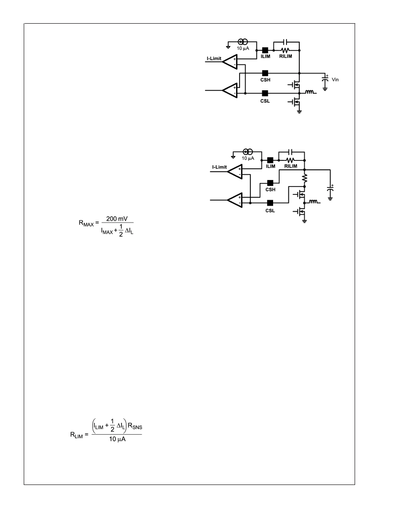
CURRENT SENSING
The inductor current information is extracted by the current
sense pins CSH and CSL. As shown in Figure 1 and Figure
2, current sensing is accomplished by either sensing the V
ds
of the top FET, or sensing the voltage across a current sense
resistor connected from V
to the drain of the top FET. Both
approaches have advantages and disadvantages that need
to be weighed for each specific application. The advantage
of sensing current through the top FET is reduced parts
count, board space, and cost but it also has the disadvan-
tage of accuracy. Using a current sense resistor is the op-
posite, improving current sense accuracy but requiring addi-
tional parts, cost, and board space. The use of a current
sense resistor has the additional disadvantage of increasing
power loss and thus decreasing efficiency.
To ensure linear operation of the current amplifier, the cur-
rent sense voltage input should not exceed 200 mV. There-
fore, the R
of the top FET or the current sense resistor
must be calculated carefully to ensure that, when the top
FET is conducting the maximum current for that application,
the current sense voltage does not exceed 200 mV.
Assuming a maximum of 200 mV across the CSL/R
resistor, the maximum allowable resistance can be calcu-
lated as follows:
Where I
MAX
is the maximum expected load current, including
an overload multiplier (typically 120%), and
I
L
is the induc-
tor ripple current.
Note that the above equation defines only the maximum
allowable value and not necessarily the recommended
value. As the resistance increases, so do the switching
losses.
CURRENT LIMITING
There is a leading edge blanking circuit that forces the top
FET to be on for at least 180 ns. Beyond this minimum on
time, the output of the PWM comparator is used to turn off
the top FET. With an external resistor connected between
the ILIM pin and the CSH pin the 10 μA current sink on the
ILIM pin produces a voltage across the resistor to serve as
the reference voltage for current limit. Adding a 10 nF ca-
pacitor across this resistor filters unwanted noise that could
improperly trip the current limit comparator. Current limit is
activated if the inductor current is too high causing the
voltage at the CSL pin to be lower than that of the ILIM pin,
toggling the comparator thus turning off the top FET imme-
diately. The comparator is disabled either when the top FET
is turned off or during the leading edge blanking time. The
equation for the current limit resistor, RLIM, is as follows:
NEGATIVE CURRENT LIMIT
The purpose of negative current limit is to ensure that the
inductor does not saturate during negative current flow caus-
ing excessive current to flow through the bottom FET. The
negative current limit is realized through sensing the bottom
FET V
ds
. An internally generated 100mV (typical) reference
is used to compare with the bottom FET V
ds
when it is on.
Upon sensing too high a V
ds
, the bottom FET is turned off.
The negative current limit is only activated in force PWM
mode.
OVER VOLTAGE PROTECTION (OVP)
The LM3075 responds to over-voltage events by attempting
to recover without the need to restart the IC. There is a trip
point at approximately 111% (typical) of V
that, once
reached, causes the circuit to shut off the HDRV FET and
turn on the LDRV FET immediately to drive the bottom FET
to discharge the output capacitor through the filter inductor.
The system stays in this configuration until the output falls
below approximately 108% (typical) of V
. Once this lower
level has been reached, the system resumes operation in
either DCM or CCM. This scenario repeats until the cause of
the over-voltage condition is removed.
UNDER VOLTAGE PROTECTION
When an under-voltage event is detected by the LM3075
and the under-voltage protection (UVP) is in ready mode, the
IC attempts to restart the entire system. It does so by shut-
ting off both the LDRV and HDRV FETs until the soft-start
capacitor has discharged below a level of 60mV (typical). At
this point, the IC shuts off the UVP and restarts the system
as though it had just been powered up. The UVP is re-
engaged once the soft-start capacitor voltage reaches a
20162308
FIGURE 1. Current Sensing by Vds of the Top FET
20162309
FIGURE 2. Current Sensing by External Sense Resistor
L
www.national.com
11
相關PDF資料 |
PDF描述 |
|---|---|
| LM3080 | Operational Transconductance Amplifier |
| LM3080AN | Operational Transconductance Amplifier |
| LM3080M | CAP 16V 470UF SOLID ELECT AXIAL |
| LM3080N | Operational Transconductance Amplifier |
| LM3086 | LM3045/LM3046/LM3086 Transistor Arrays |
相關代理商/技術參數(shù) |
參數(shù)描述 |
|---|---|
| LM3075N/A+ | 制造商:未知廠家 制造商全稱:未知廠家 功能描述:FM Receiver Circuit |
| LM3075N/B+ | 制造商:未知廠家 制造商全稱:未知廠家 功能描述:FM Receiver Circuit |
| LM3075N-01/A+ | 制造商:未知廠家 制造商全稱:未知廠家 功能描述:FM Receiver Circuit |
| LM3075N-01/B+ | 制造商:未知廠家 制造商全稱:未知廠家 功能描述:FM Receiver Circuit |
| LM307AH | 制造商:Texas Instruments 功能描述: |
發(fā)布緊急采購,3分鐘左右您將得到回復。