- 您現(xiàn)在的位置:買賣IC網(wǎng) > PDF目錄377798 > LXT381 (Intel Corp.) Octal E1 Line Interface Unit PDF資料下載
參數(shù)資料
| 型號: | LXT381 |
| 廠商: | Intel Corp. |
| 英文描述: | Octal E1 Line Interface Unit |
| 中文描述: | 八進(jìn)制E1線路接口裝置 |
| 文件頁數(shù): | 28/36頁 |
| 文件大小: | 218K |
| 代理商: | LXT381 |
第1頁第2頁第3頁第4頁第5頁第6頁第7頁第8頁第9頁第10頁第11頁第12頁第13頁第14頁第15頁第16頁第17頁第18頁第19頁第20頁第21頁第22頁第23頁第24頁第25頁第26頁第27頁當(dāng)前第28頁第29頁第30頁第31頁第32頁第33頁第34頁第35頁第36頁

LXT381
—
Octal E1 Line Interface
28
Datasheet
Average
transmitter
power supply
current
1
75
,
coax cable
120
,
TWP cable
75
,
coax cable
120
,
TWP cable
I
TVCC
-
-
-
125
100
265
210
-
-
mA
mA
mA
mA
100% 1
’
s density
100% 1
’
s density
50% 1
’
s density
50% 1
’
s density
Average core power supply current
1
I
VCC
-
80
100
mA
Average I/O power supply current
1, 2
I
VCCIO
18
25
mA
Output load at TTIP and TRING
Rl
40
-
-
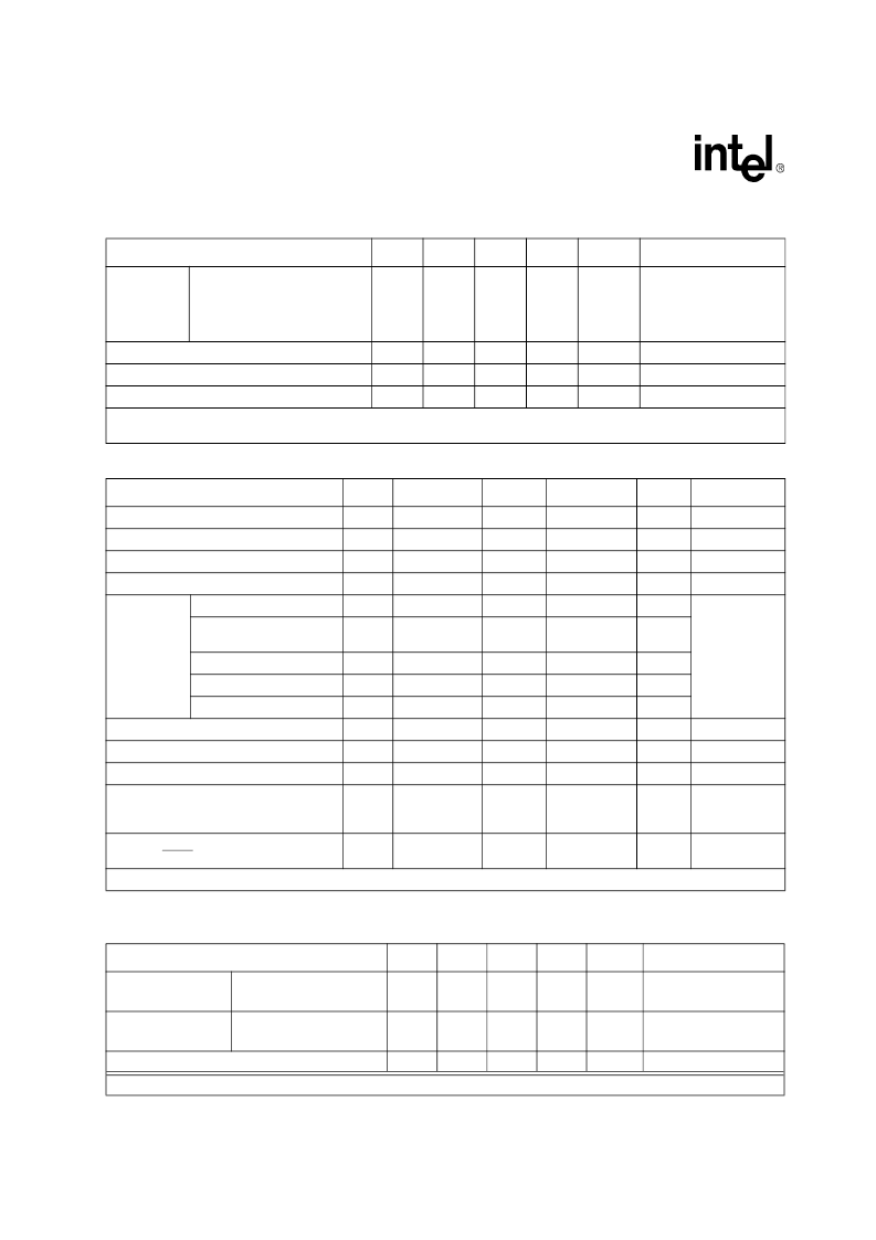
Table 10. DC Characteristics
Parameter
Sym
Min.
Typ.
Max.
Unit
Test Condition
High level input voltage
V
IH
2
-
-
V
Low level input voltage
V
IL
-
-
0.8
V
High level output voltage
1
V
OH
2.4
V
CC
IO
V
I
OUT
= 400μA
Low level output voltage
1
V
OL
-
-
0.4
V
I
OUT
= 1.6mA
LOOP 0-7
Low level input voltage
V
INL
–
–
1/3VCC-0.2
V
The VCC
supply refers to
VCCIO0 or
VCCIO1 only.
Midrange level input
voltage
V
INM
1/3VCC+0.2
1/2VCC
2/3VCC-0.2
V
High level input voltage
V
INH
2/3VCC+0.2
-
-
V
Low level input current
I
INL
–
–
50
μA
High level input current
I
INH
–
–
50
μA
Input leakage current
I
IL
-10
–
+10
μA
Tri state leakage current
I
HZ
-10
–
+10
μA
Tri state output current
I
HZ
-
-
1
μA
TTIP, TRING
Line short circuit current
-
-
-
50
mA
RMS
2 x 11
series
resistors and
1:2 transformer
Input leakage:
TMS TDI TRST
-
-
-
50
μA
1. Output drivers will output CMOS logic levels into CMOS loads.
Table 11. Transmit Transmission Characteristics
Parameter
Sym
Min.
Typ.
Max.
Unit
Test Condition
Output pulse
amplitude
75
120
-
2.14
2.7
2.37
3.0
2.60
3.3
V
V
Tested at the line side
Peak voltage of a
space
75
120
-
-0.237
-0.3
-
0.237
0.3
V
V
Transmit amplitude variation with supply
-
-1
-
+1
%
1. Guaranteed by design and other correlation methods.
Table 9. Recommended Operating Conditions (Continued)
Parameter
Sym
Min.
Typ.
Max.
Unit
Test Condition
1. Current consumption over the full operating temperature and power supply voltage range.
2. Digital inputs are within 10% of the supply rails and digital outputs are driving a 50pF load.
相關(guān)PDF資料 |
PDF描述 |
|---|---|
| LXT386 | QUAD T1/E1/J1 Transceiver |
| LXT400 | All Rate Extended Range Switched 56/DDS Transceiver |
| LXT441 | Switched 56/DDS Integrated DSU/CSU |
| LXT6155 | 155 Mbps SDH/SONET/ATM Transceiver |
| LXT6234 | E-Rate Multiplexer |
相關(guān)代理商/技術(shù)參數(shù) |
參數(shù)描述 |
|---|---|
| LXT381BE | 制造商:INTEL 制造商全稱:Intel Corporation 功能描述:Octal E1 Line Interface Unit |
| LXT381LE | 制造商:INTEL 制造商全稱:Intel Corporation 功能描述:Octal E1 Line Interface Unit |
| LXT384/LXT386/LXT388 | 制造商:未知廠家 制造商全稱:未知廠家 功能描述:LXT384/LXT386/LXT388 - LXT384/6/8 Twisted Pair Interface Without Component Changes |
| LXT384BE | 制造商:未知廠家 制造商全稱:未知廠家 功能描述:Telecomm/Datacomm |
| LXT384LE | 制造商:未知廠家 制造商全稱:未知廠家 功能描述:Telecomm/Datacomm |
發(fā)布緊急采購,3分鐘左右您將得到回復(fù)。