- 您現(xiàn)在的位置:買賣IC網 > PDF目錄377826 > M41T11MH6F (意法半導體) Serial Real Time Clock with 56 Bytes of NVRAM PDF資料下載
參數資料
| 型號: | M41T11MH6F |
| 廠商: | 意法半導體 |
| 英文描述: | Serial Real Time Clock with 56 Bytes of NVRAM |
| 中文描述: | 串行實時時鐘與56字節(jié)的NVRAM |
| 文件頁數: | 15/29頁 |
| 文件大?。?/td> | 154K |
| 代理商: | M41T11MH6F |
第1頁第2頁第3頁第4頁第5頁第6頁第7頁第8頁第9頁第10頁第11頁第12頁第13頁第14頁當前第15頁第16頁第17頁第18頁第19頁第20頁第21頁第22頁第23頁第24頁第25頁第26頁第27頁第28頁第29頁
M41T11
Clock operation
15/29
Table 3.
3.1
Clock calibration
The M41T11 is driven by a quartz controlled oscillator with a nominal frequency of
32,768Hz. The devices are tested not to exceed 35 ppm (parts per million) oscillator
frequency error at 25°C, which equates to about ±1.53 minutes per month. With the
calibration bits properly set, the accuracy of each M41T11 improves to better than ±2 ppm
at 25°C.
The oscillation rate of any crystal changes with temperature (see
Figure 12 on page 17
).
Most clock chips compensate for crystal frequency and temperature shift error with
cumbersome trim capacitors. The M41T11 design, however, employs periodic counter
correction. The calibration circuit adds or subtracts counts from the oscillator divider circuit
at the divide by 256 stage, as shown in
Figure 13 on page 17
. The number of times pulses
are blanked (subtracted, negative calibration) or split (added, positive calibration) depends
upon the value loaded into the five-bit Calibration byte found in the Control Register. Adding
counts speeds the clock up, subtracting counts slows the clock down.
The Calibration byte occupies the five lower order bits (D4-D0) in the Control register (Addr
7). This byte can be set to represent any value between 0 and 31 in binary form. Bit D5 is a
Sign Bit; '1' indicates positive calibration, '0' indicates negative calibration. Calibration
occurs within a 64minute cycle. The first 62 minutes in the cycle may, once per minute, have
one second either shortened by 128 or lengthened by 256 oscillator cycles. If a binary '1' is
loaded into the register, only the first 2 minutes in the 64 minute cycle will be modified; if a
binary 6 is loaded, the first 12 will be affected, and so on.
Therefore, each calibration step has the effect of adding 512 or subtracting 256 oscillator
cycles for every 125,829,120 actual oscillator cycles, that is +4.068 or –2.034 ppm of
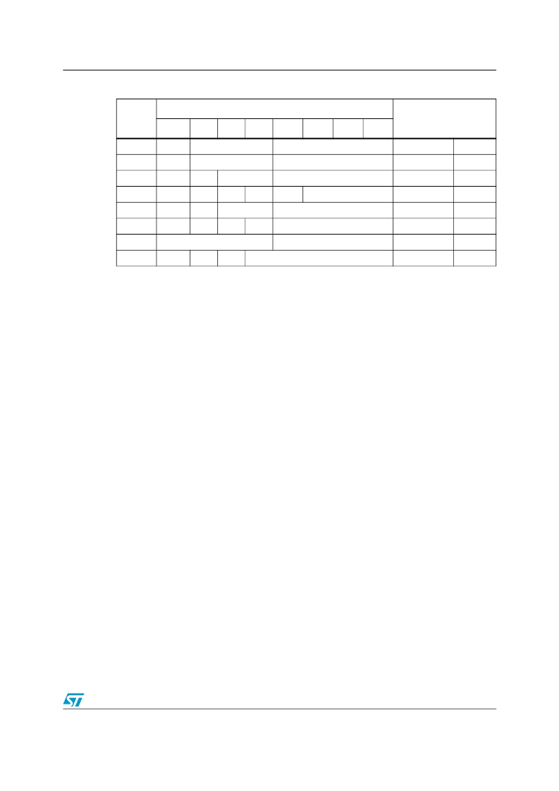
Register map
(1)
1.
Keys:
S = SIGN Bit
FT = FREQUENCY TEST Bit
ST = STOP Bit
OUT = Output level
X = Don’t care
CEB = Century Enable Bit
CB = Century Bit
Address
Data
Function/range
BCD format
D7
D6
D5
D4
D3
D2
D1
D0
0
ST
10 seconds
Seconds
Seconds
00-59
1
X
10 minutes
Minutes
Minutes
00-59
2
CEB
(2)
2.
When CEB is set to '1', CB will toggle from '0' to '1' or from '1' to '0' every 100 years (dependent upon the
initial value set). When CEB is set to '0', CB will not toggle.When CEB is set to '1', CB will toggle from '0' to
'1' or from '1' to '0' every 100 years (dependent upon the initial value set). When CEB is set to '0', CB will
not toggle.
CB
10 hours
Hours
Century/hours 0-1/00-23
3
X
X
X
X
X
Day
Day
01-07
4
X
X
10 date
Date
Date
01-31
5
X
X
X
10 M.
Month
Month
01-12
6
10 years
Years
Year
00-99
7
OUT
FT
S
Calibration
Control
相關PDF資料 |
PDF描述 |
|---|---|
| M41T256YMH7E | 256 Kbit 32K x8 SERIAL RTC |
| M41T256YMH7F | 256 Kbit 32K x8 SERIAL RTC |
| M41T256YMT7E | 256 Kbit 32K x8 SERIAL RTC |
| M41T256YMT7F | 256 Kbit 32K x8 SERIAL RTC |
| M41T315V | Serial access phantom RTC supervisor |
相關代理商/技術參數 |
參數描述 |
|---|---|
| M41T11MH6F-CUT TAPE | 制造商:ST 功能描述:M41T11 Series 2 to 5.5 V Serial I2C Real Time Clock Surface Mount - SOH-28 |
| M41T11MH6TR | 制造商:STMicroelectronics 功能描述:REAL TIME CLOCK SERL 64BYTE 28PIN SOH - Tape and Reel |
| M41T11SH | 制造商:STMICROELECTRONICS 制造商全稱:STMicroelectronics 功能描述:512 bit 64b x8 Serial Access TIMEKEEPER SRAM |
| M41T256Y | 制造商:STMICROELECTRONICS 制造商全稱:STMicroelectronics 功能描述:256 Kbit 32K x8 SERIAL RTC |
| M41T256Y_07 | 制造商:STMICROELECTRONICS 制造商全稱:STMicroelectronics 功能描述:256Kbit (32K x 8) serial RTC |
發(fā)布緊急采購,3分鐘左右您將得到回復。