- 您現(xiàn)在的位置:買賣IC網(wǎng) > PDF目錄370963 > M51971FP (Mitsubishi Electric Corporation) MOTOR SPEED CONTROL PDF資料下載
參數(shù)資料
| 型號: | M51971FP |
| 廠商: | Mitsubishi Electric Corporation |
| 英文描述: | MOTOR SPEED CONTROL |
| 中文描述: | 電機轉(zhuǎn)速控制 |
| 文件頁數(shù): | 11/13頁 |
| 文件大?。?/td> | 387K |
| 代理商: | M51971FP |

MOTOR SPEED CONTROL
M51971L/FP
MITSUBISHI <CONTROL / DRIVER IC>
Hint for designing a stabilized speed control
system
(Method for determining the filter constants (C
F1
, C
F2
and R
F
) at
pin
)
8
The filter constants at pin
system stability.
must be determined to satisfy the
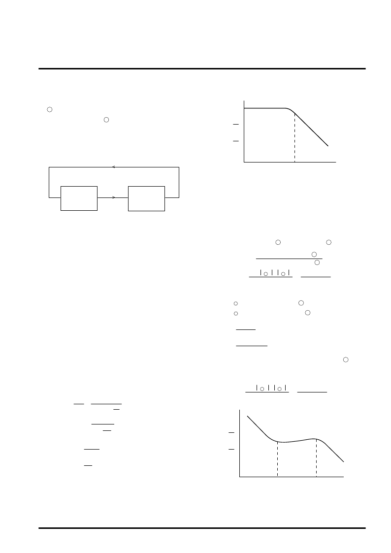
1. Transfer Function of the Motor Speed Control
System
8
The motor speed control system is a negative feedback system
including a control circuit and a motor.
As the condition necessary for stable negative feedback, the phase
must be generally 180 or less in the frequency area where the
gain of open-loop transfer function (G
C
(S)
G
M
(S)) is 1 or more.
2. Transfer Function of Motor
If the motor armature current and angular velocity are assumed to
be la and
ω
v, respectively, the following equation is established.
T
g
= K
T
l
a
= (SJ+D)
ω
v
(1)
Where:T
g
: Torque generated in the motor
K
T
: Proportional constant between the torque genera-
ted in the motor and the armature current
J : Inertia moment of Motor and load
D : Coefficient of viscosity friction
If the number of poles in the tacho-generator is assumed to be P,
the relation of
ω
= P
ω
v exists between tacho-generator angular
frequency
ω
and motor angular velocity
ω
v and, therefore, the
motor transfer function (transfer function including motor and
tacho-generator) G
M
(S) takes a single-pole transfer function as
follows:
Where:
l
a
ω
=
D
(1+S
)
P
K
T
D
J
=
1 +
K
M
ω
M
S
G
M
(S) =
(2)
(3)
D
P
K
T
K
M
=
J
D
ω
M
=
(4)
(5)
3. Transfer Function of Control Circuit Using the
M51971
If input information is assumed to be given continuously (the tacho-
generator frequency is assumed to be infinitely high), the transfer
function from the input at pin
to the output at pin
4
is as follows:
9
(input frequency at pin )
(output voltage at pin )
G
C(M51971)
(S)
(6)
4
9
=
C
F1
+ C
F2
T
τ
( I
C
+ I
d
)
8
8
x
S(1 + S/
ω
F2
)
1 + S/
ω
F1
Where :
T
τ
: Timer pulse width 1.10 x R
τ
x C
τ
l
C
: Charging current at pin
l
d
: Discharging current at pin
8
8
8
8
R
F
C
F2
1
ω
F1
R
F
C
F1
C
F2
C
F1
+C
F2
ω
F2
If the gain of the circuit connected to the back of pin
M51971 is assumed to be K
CP
, transfer function G
C
(S) for the
entire circuit is as follows:
of the
9
G
C
(S) = K
CP
(7)
C
F1
+ C
F2
T
τ
( I
C
+ I
d
)
8
8
x
S(1 + S/
ω
F2
)
1 + S/
ω
F1
x
≡
≡
≡
Control circuit
- G
C
(S)
Motor
G
M
(S)
Motor speed control system
l
M
(
ω
)
log
ω
ω
M
Approximate motor transfer function
l
C
(
ω
)
log
ω
ω
F1
Approximate transfer function of control circuit
ω
F2
相關(guān)PDF資料 |
PDF描述 |
|---|---|
| M51971L | MOTOR SPEED CONTROL |
| M51977FP | SWITCHING REGULATIR CONTROL |
| M51977P | SWITCHING REGULATIR CONTROL |
| M51978FP | RADIATION HARDENED HIGH EFFICIENCY, 5 AMP SWITCHING REGULATORS |
| M51978P | RADIATION HARDENED HIGH EFFICIENCY, 5 AMP SWITCHING REGULATORS |
相關(guān)代理商/技術(shù)參數(shù) |
參數(shù)描述 |
|---|---|
| M51971L | 制造商:MITSUBISHI 制造商全稱:Mitsubishi Electric Semiconductor 功能描述:MOTOR SPEED CONTROL |
| M51977FP | 制造商:MITSUBISHI 制造商全稱:Mitsubishi Electric Semiconductor 功能描述:SWITCHING REGULATIR CONTROL |
| M51977P | 制造商:Panasonic Industrial Company 功能描述:IC SUBBING WITH PQVIM51977P |
| M51978FP | 制造商:MITSUBISHI 制造商全稱:Mitsubishi Electric Semiconductor 功能描述:SWITCHING REGULATOR CONTROL |
| M51978P | 制造商:MITSUBISHI 制造商全稱:Mitsubishi Electric Semiconductor 功能描述:SWITCHING REGULATOR CONTROL |
發(fā)布緊急采購,3分鐘左右您將得到回復。