- 您現(xiàn)在的位置:買賣IC網(wǎng) > PDF目錄370963 > M51971FP (Mitsubishi Electric Corporation) MOTOR SPEED CONTROL PDF資料下載
參數(shù)資料
| 型號(hào): | M51971FP |
| 廠商: | Mitsubishi Electric Corporation |
| 英文描述: | MOTOR SPEED CONTROL |
| 中文描述: | 電機(jī)轉(zhuǎn)速控制 |
| 文件頁數(shù): | 7/13頁 |
| 文件大?。?/td> | 387K |
| 代理商: | M51971FP |

MOTOR SPEED CONTROL
M51971L/FP
MITSUBISHI <CONTROL / DRIVER IC>
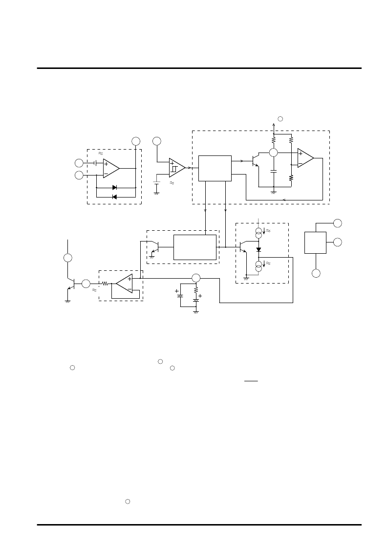
Brief Description on M51971 Operation
Block Description
FG amplifier
The FG amplifier consists of an operational amplifier, revel shift
circuit and diode for waveform clip.
When a DC block capacitor is connected to pin , output DC
voltage at pin
becomes higher than DC voltage at pin
(
≈
1.9V
≈
3V
BE
).
AC signals centering around the GND can be therefore amplified
easily. The clipper diode limits the output signal amplitude to
±
0.7V (V
BE
) max. and rapidly charges DC block capacitor with
power supply turned ON.
by V
LS
Schmitt circuit
The Schmitt circuit is a comparator with histeresis, and has ON
level of V
LS
+ 20mV and OFF level of V
LS
- 20mV.
Timer
The timer generates basic time necessary for controlling the
speed.
This timer is a one-shot circuit triggered with input signals and
generates pulse of 1.1 C
τ
R
τ
in pulse width.
Constant current control circuit
The constant current control circuit is controlled with output of timer
circuit. The circuit generates, at pin , source current of I
1
– I
2
(
≈
190
μ
A) for the period without one-shot pulse and generates sink
current of I
2
(
≈
16
μ
A) for the period with one-shot pulse.
The ratio of I
1
to I
2
is characteristic to the IC. The frequency of the
tacho-generator to be set is determined by the one-short pulse
width and this current ratio (I
1
/ I
2
≈
12.6).
Where:
T
G
: Tacho-generator signal frequency (set value)
T
τ
: One-short pulse width
Over-shoot prevention circuit
The over-shoot prevention circuit operates when over-shoot is
large in particular, e.g. the motor is suddenly released from lock
status.
Q
3
is set to ON for the period of one-short pulse width (T
τ
) when
the signal period of the tacho-generator in a motor is shorter than
the one-shot pulse. Generally, electric charge of C
F1
is discharged
for this period due to R
F
C
F2
>>T
τ
.
Buffer amplifier
The buffer circuit is a voltage follower circuit using an operational
amplifier. The input current is very small (10nA max.) and the
circuit can drive the output current of 20mA.
T
G
= T
τ
x
≈
1.09 x T
τ
I
1
–I
2
I
1
2
1
3
8
1
2
3
Schmitt
input
4
Schmitt
circuit
V
LS
1.9V
5
10
7
6
M
9
8
FG amplifier
Non-inverted input
Inverted input
D
1
D
2
V
LS
Operational
amplifier
Amplifier
output
Timer
Logic for timer
E
C
Q
1
B
D
C
τ
R
τ
7.5k
comparator
A
A’
Timer output
Over-shoot
prevention signal
Over-shoot prevention circuit
Buffer
100
H
G
Q
3
OP
C
F1
C
F2
R
F
206
μ
A
16
μ
A
I
2
I
1
Q
2
Logic for over-shoot
prevention
Constant current
control
To pin
15k
Stabilized voltage
GND
Power
supply
Stabilized
power
supply
1.9V
I
6
相關(guān)PDF資料 |
PDF描述 |
|---|---|
| M51971L | MOTOR SPEED CONTROL |
| M51977FP | SWITCHING REGULATIR CONTROL |
| M51977P | SWITCHING REGULATIR CONTROL |
| M51978FP | RADIATION HARDENED HIGH EFFICIENCY, 5 AMP SWITCHING REGULATORS |
| M51978P | RADIATION HARDENED HIGH EFFICIENCY, 5 AMP SWITCHING REGULATORS |
相關(guān)代理商/技術(shù)參數(shù) |
參數(shù)描述 |
|---|---|
| M51971L | 制造商:MITSUBISHI 制造商全稱:Mitsubishi Electric Semiconductor 功能描述:MOTOR SPEED CONTROL |
| M51977FP | 制造商:MITSUBISHI 制造商全稱:Mitsubishi Electric Semiconductor 功能描述:SWITCHING REGULATIR CONTROL |
| M51977P | 制造商:Panasonic Industrial Company 功能描述:IC SUBBING WITH PQVIM51977P |
| M51978FP | 制造商:MITSUBISHI 制造商全稱:Mitsubishi Electric Semiconductor 功能描述:SWITCHING REGULATOR CONTROL |
| M51978P | 制造商:MITSUBISHI 制造商全稱:Mitsubishi Electric Semiconductor 功能描述:SWITCHING REGULATOR CONTROL |
發(fā)布緊急采購,3分鐘左右您將得到回復(fù)。