- 您現(xiàn)在的位置:買賣IC網(wǎng) > PDF目錄11587 > MAX3420EETG+ (Maxim Integrated Products)IC USB PERIPH CONTROLLER 24TQFN PDF資料下載
參數(shù)資料
| 型號: | MAX3420EETG+ |
| 廠商: | Maxim Integrated Products |
| 文件頁數(shù): | 17/22頁 |
| 文件大小: | 0K |
| 描述: | IC USB PERIPH CONTROLLER 24TQFN |
| 產(chǎn)品培訓模塊: | Lead (SnPb) Finish for COTS Obsolescence Mitigation Program |
| 標準包裝: | 75 |
| 控制器類型: | USB 外設控制器 |
| 接口: | USB/串行 |
| 電源電壓: | 3 V ~ 3.6 V |
| 電流 - 電源: | 15mA |
| 工作溫度: | -40°C ~ 85°C |
| 安裝類型: | 表面貼裝 |
| 封裝/外殼: | 24-WFQFN 裸露焊盤 |
| 供應商設備封裝: | 24-TQFN-EP(4x4) |
| 包裝: | 管件 |
| 產(chǎn)品目錄頁面: | 1407 (CN2011-ZH PDF) |
| 配用: | MAX3420EEVKIT-2+-ND - EVAL KIT FOR MAX3420E |
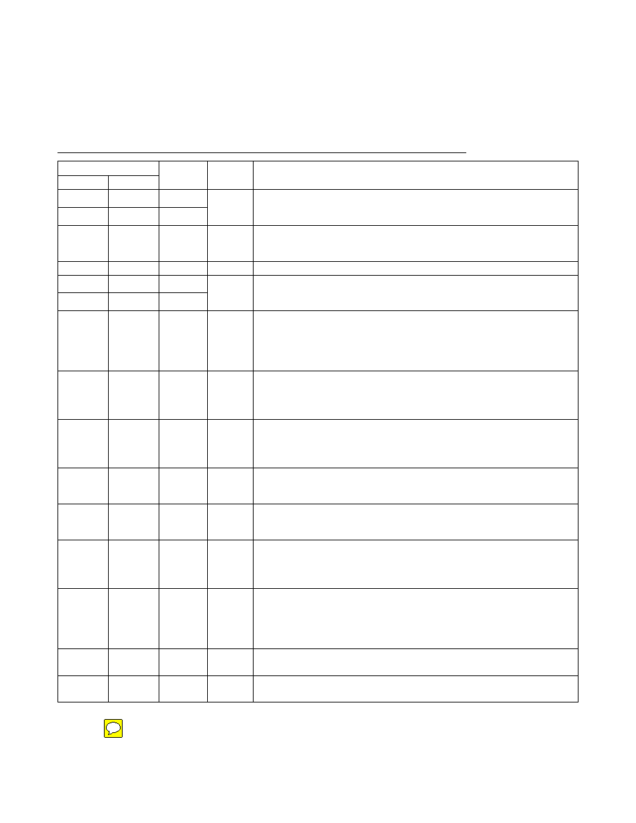
USB Peripheral Controller
with SPI Interface
Pin Description
PIN
TQFN-EP
LQFP
NAME
INPUT/
OUTPUT
FUNCTION
1
GPOUT0
2
GPOUT1
Output
General-Purpose Push-Pull Outputs. GPOUT3–GPOUT0 logic levels are
referenced to the voltage on VL. The SPI master controls the GPOUT3–GPOUT0
states by writing to bit 3 through bit 0 of the IOPINS (R20) register.
3
3, 4
VL
Input
Level-Translator Reference Voltage. Connect VL to the system’s 1.71V to 3.6V
logic-level power supply. Bypass VL to ground with a 0.1μF capacitor as close
to the VL pin as possible.
4, 14
5, 6, 18, 19
GND
Input
Ground
5
7
GPOUT2
6
8
GPOUT3
Output
General-Purpose Push-Pull Outputs. GPOUT3–GPOUT0 logic levels are
referenced to the voltage on VL. The SPI master controls the GPOUT3–GPOUT0
states by writing to bit 3 through bit 0 of the IOPINS (R20) register.
7
10
RES
Input
Device Reset. Drive RES low to clear all of the internal registers except for
PINCTL (R17), USBCTL (R15), and SPI logic. See the Device Reset section for a
description of resets available on the MAX3420E. Note: The MAX3420E is
internally reset if either VCC of VL is not present. The register file is not
accessible under these conditions.
8
11
SCLK
Input
SPI Serial-Clock Input. An external SPI master supplies this clock with
frequencies up to 26MHz. The logic level is referenced to the voltage on VL.
Data is clocked into the SPI slave interface on the positive edge of SCLK. Data
is clocked out of the SPI slave interface on the falling edge of SCLK.
9
12
SS
Input
SPI Slave-Select Input. The SS logic level is referenced to the voltage on VL.
When SS is driven high, the SPI slave interface is not selected and SCLK
transitions are ignored. An SPI transfer begins with a high-to-low SS transition
and ends with a low-to-high SS transition.
10
13
MISO
Output
SPI Serial-Data Output (Master-In, Slave-Out). MISO is a push-pull output. MISO
is tri-stated in half-duplex mode or when SS = 1. The MISO logic level is
referenced to the voltage on VL.
11
14
MOSI
Input or
Input/
Output
SPI Serial-Data Input (Master-Out, Slave-In). The logic level on MOSI is
referenced to the voltage on VL. MOSI can also be configured as a bidirectional
MOSI/MISO input and output.
12
15
GPX
Output
General-Purpose Multiplexed Output. The internal MAX3420E signal that
appears on GPX is programmable by writing to the GPXB and GPXA bits of the
PINCTL (R17) register. GPX indicates one of four signals: OPERATE (00,
default), VBUS_DET (01), BUSACT (10), and SOF (11).
13
17
INT
Output
Interrupt Output. In edge mode, the logic level on INT is referenced to the
voltage
on VL. In edge mode, INT is a push-pull output with programmable polarity. In
level mode, INT is open-drain and active low. Set the IE bit in the CPUCTL
(R16) register to enable INT.
15
20
D-
Input/
Output
USB D- Signal. Connect D- to a USB “B” connector through a 33
±1% series
resistor.
16
21
D+
Input/
Output
USB D+ Signal. Connect D+ to a USB “B” connector through a 33
±1% series
resistor. The 1.5k
D+ pullup resistor is internal to the device.
MAX3420E
4
Maxim Integrated
相關PDF資料 |
PDF描述 |
|---|---|
| PIC12F629-E/SN | IC MCU CMOS 8BIT 1K FLASH 8-SOIC |
| PIC12LC508A-04I/MF | IC MCU OTP 512X12 LV 8DFN |
| PIC16F631-E/P | IC PIC MCU FLASH 1KX14 20DIP |
| PIC16C620A-04I/SO | IC MCU OTP 512X14 COMP 18SOIC |
| PIC12CE518-04I/SN | IC MCU OTP 512X12 W/EE 8SOIC |
相關代理商/技術參數(shù) |
參數(shù)描述 |
|---|---|
| MAX3420EETG+ | 功能描述:外圍驅動器與原件 - PCI USB Peripheral Controller w/SPI RoHS:否 制造商:PLX Technology 工作電源電壓: 最大工作溫度: 安裝風格:SMD/SMT 封裝 / 箱體:FCBGA-1156 封裝:Tray |
| MAX3420EETG+T | 功能描述:外圍驅動器與原件 - PCI USB Peripheral Controller w/SPI RoHS:否 制造商:PLX Technology 工作電源電壓: 最大工作溫度: 安裝風格:SMD/SMT 封裝 / 箱體:FCBGA-1156 封裝:Tray |
| MAX3420EETG-T | 功能描述:外圍驅動器與原件 - PCI RoHS:否 制造商:PLX Technology 工作電源電壓: 最大工作溫度: 安裝風格:SMD/SMT 封裝 / 箱體:FCBGA-1156 封裝:Tray |
| MAX3420EEVKIT | 制造商:Maxim Integrated Products 功能描述:MAX3420E EVAL KIT - Bulk |
| MAX3420EEVKIT-2+ | 功能描述:界面開發(fā)工具 MAX3420E Eval Kit RoHS:否 制造商:Bourns 產(chǎn)品:Evaluation Boards 類型:RS-485 工具用于評估:ADM3485E 接口類型:RS-485 工作電源電壓:3.3 V |
發(fā)布緊急采購,3分鐘左右您將得到回復。