- 您現(xiàn)在的位置:買賣IC網(wǎng) > PDF目錄1946 > MAX9952FCCB+T (Maxim Integrated Products)IC PMU DUAL 64TQFP PDF資料下載
參數(shù)資料
| 型號(hào): | MAX9952FCCB+T |
| 廠商: | Maxim Integrated Products |
| 文件頁(yè)數(shù): | 11/24頁(yè) |
| 文件大小: | 0K |
| 描述: | IC PMU DUAL 64TQFP |
| 標(biāo)準(zhǔn)包裝: | 750 |
| 系列: | * |
第1頁(yè)第2頁(yè)第3頁(yè)第4頁(yè)第5頁(yè)第6頁(yè)第7頁(yè)第8頁(yè)第9頁(yè)第10頁(yè)當(dāng)前第11頁(yè)第12頁(yè)第13頁(yè)第14頁(yè)第15頁(yè)第16頁(yè)第17頁(yè)第18頁(yè)第19頁(yè)第20頁(yè)第21頁(yè)第22頁(yè)第23頁(yè)第24頁(yè)

MAX9951/MAX9952
Dual Per-Pin Parametric
Measurement Units
19
Maxim Integrated
A digital output decoded from the range select bits,
EXTSEL_, indicates when to activate the booster.
CCOM_ serves as an input to an external buffer through
an internal 50
Ω current-limit series resistor. Connect the
external buffer output to the external current-sense resis-
tor, REXT, and to R_X. Connect the other side of REXT to
FORCE_. Ensure that the external switch is low leakage.
Voltage Clamps
The voltage clamps limit FORCE_ and operate over the
entire specified current range. Set the clamp voltages
externally at CLHI_ and CLLO_. The voltage at FORCE_
triggers the clamps independent of the voltage at
SENSE_. When enabled, the clamps function in FI
mode only. Use clamp voltages of 0.7V above and
below the FORCE_ voltage range to ensure proper
operation of the PMU.
Current Limit
The FORCE_ current-limiting circuitry, 92mA (maximum),
ensures a well-behaved MSR_ output for currents
between the full current range and the current limits. For
currents greater than the full-scale current, the MSR_
voltage is greater than +4V, and for currents less than
the full-scale current, the MSR_ voltage is less than -4V.
Additionally, serial interface bit B2 enables a range-sen-
sitive current limit of 2.5 times the nominal current range.
Table 9 shows the current-limit operation.
Independent Control of the Feedback
Switch and the Measure Switch
Two single-pole-double-throw (SPDT) switches deter-
mine the mode of operation of the PMU. One switch
determines whether the sensed DUT current or DUT
voltage feeds back to the input, and thus determines
whether the MAX9951/MAX9952 force current or volt-
age. The other switch determines whether MSR_ sens-
es the DUT current or DUT voltage.
Independent control of these switches and the HI-
ZFORCE state permits flexible modes of operation
beyond the traditional force-voltage/measure-current
(FVMI) and force-current/measure-voltage (FIMV)
modes. The MAX9951/MAX9952 support the following
eight modes:
FVMI
FIMV
FVMV
FIMI
FNMV
FNMI (range E only)
Terminate/Measure V
Terminate/Measure I
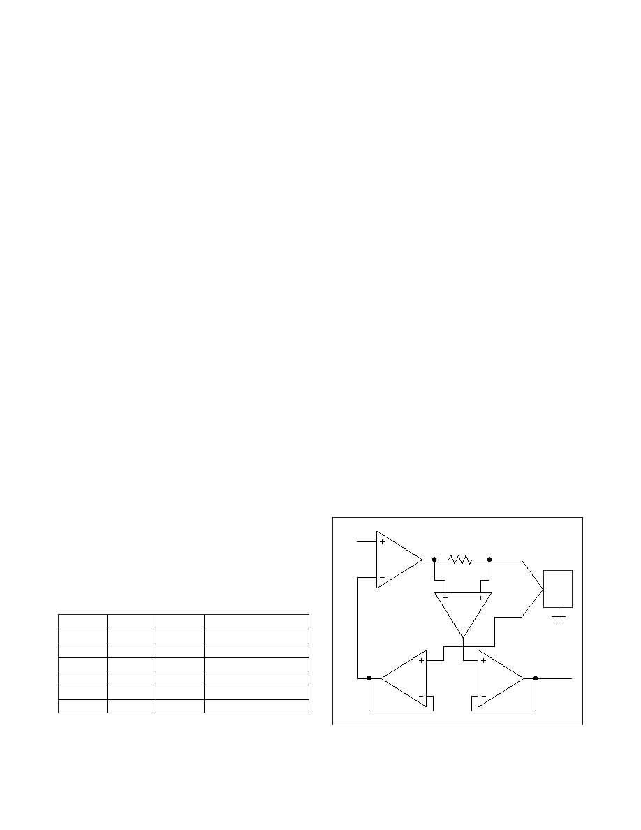
Figure 6 shows the internal path structure for force-volt-
age/measure-current mode. In force-voltage/measure-
current mode, the current across the appropriate
external sense resistor (R_A to R_E) provides a voltage
at MSR_. SENSE_ samples the voltage at the DUT and
feeds the buffered result back to the negative input of
the voltage amplifier. The voltage at MSR_ is propor-
tional to the FORCE_ current in accordance with the fol-
lowing formula:
VMSR_ = IFORCE_ x RSENSE x 4
Figure 7 shows the internal path structure for the force-
current/measure-voltage mode. In force-current/mea-
sure-voltage mode, the appropriate external sense
resistor (R_A to R_E) provides a feedback voltage to
Table 9. Current Limit
FMODE
RANGE
B2
CURRENT LIMIT
X
Any
0
65mA to 92mA
0
A
1
65mA to 92mA
0B
1
5mA
0
C
1
500A
0
D
1
50A
0
E
1
5A
IN1_
AV = +4
DUT
DUTGND
MSR_
FORCE_
SENSE_
RSENSE
Figure 6. Force-Voltage/Measure-Current Functional Diagram
相關(guān)PDF資料 |
PDF描述 |
|---|---|
| MAXQ2000-RAX+ | IC MCU 32K FLASH 68-QFN |
| MAXQ2010-RFX+ | IC MCU 16BIT 64KB FLASH 100-LQFP |
| MAXQ3120-FFN+ | IC MCU 32KB FLASH 80-MQFP |
| MAXQ3210-EMX+ | IC MCU 16BIT LP 24-DIP |
| MAXQ3212-EJX+ | IC MCU 16BIT LP 24-TSSOP |
相關(guān)代理商/技術(shù)參數(shù) |
參數(shù)描述 |
|---|---|
| MAX9952FCCB-TD | 功能描述:接口 - 專用 RoHS:否 制造商:Texas Instruments 產(chǎn)品類型:1080p60 Image Sensor Receiver 工作電源電壓:1.8 V 電源電流:89 mA 最大功率耗散: 最大工作溫度:+ 85 C 安裝風(fēng)格:SMD/SMT 封裝 / 箱體:BGA-59 |
| MAX9955BDCCB+D | 制造商:Maxim Integrated Products 功能描述:DUAL DRIVER/TERMINATOR WITH CABLE-D - Rail/Tube |
| MAX9955BDCCB-D | 功能描述:校驗(yàn)器 IC RoHS:否 制造商:STMicroelectronics 產(chǎn)品: 比較器類型: 通道數(shù)量: 輸出類型:Push-Pull 電源電壓-最大:5.5 V 電源電壓-最小:1.1 V 補(bǔ)償電壓(最大值):6 mV 電源電流(最大值):1350 nA 響應(yīng)時(shí)間: 最大工作溫度:+ 125 C 安裝風(fēng)格:SMD/SMT 封裝 / 箱體:SC-70-5 封裝:Reel |
| MAX9955BDCCB-TD | 功能描述:校驗(yàn)器 IC RoHS:否 制造商:STMicroelectronics 產(chǎn)品: 比較器類型: 通道數(shù)量: 輸出類型:Push-Pull 電源電壓-最大:5.5 V 電源電壓-最小:1.1 V 補(bǔ)償電壓(最大值):6 mV 電源電流(最大值):1350 nA 響應(yīng)時(shí)間: 最大工作溫度:+ 125 C 安裝風(fēng)格:SMD/SMT 封裝 / 箱體:SC-70-5 封裝:Reel |
| MAX9957CCB+D | 制造商:Maxim Integrated Products 功能描述:FAST DUAL DRIVER FOR ATE WITH WAVEF - Rail/Tube |
發(fā)布緊急采購(gòu),3分鐘左右您將得到回復(fù)。