- 您現(xiàn)在的位置:買賣IC網(wǎng) > PDF目錄67964 > MB96F395YSBPMC-GSE2 16-BIT, FLASH, 56 MHz, RISC MICROCONTROLLER, PQFP100 PDF資料下載
參數(shù)資料
| 型號: | MB96F395YSBPMC-GSE2 |
| 元件分類: | 微控制器/微處理器 |
| 英文描述: | 16-BIT, FLASH, 56 MHz, RISC MICROCONTROLLER, PQFP100 |
| 封裝: | 14 X 14 MM, 1.70 MM HEIGHT, 0.50 MM PITCH, PLASTIC, LQFP-100 |
| 文件頁數(shù): | 44/96頁 |
| 文件大小: | 2534K |
| 代理商: | MB96F395YSBPMC-GSE2 |
第1頁第2頁第3頁第4頁第5頁第6頁第7頁第8頁第9頁第10頁第11頁第12頁第13頁第14頁第15頁第16頁第17頁第18頁第19頁第20頁第21頁第22頁第23頁第24頁第25頁第26頁第27頁第28頁第29頁第30頁第31頁第32頁第33頁第34頁第35頁第36頁第37頁第38頁第39頁第40頁第41頁第42頁第43頁當(dāng)前第44頁第45頁第46頁第47頁第48頁第49頁第50頁第51頁第52頁第53頁第54頁第55頁第56頁第57頁第58頁第59頁第60頁第61頁第62頁第63頁第64頁第65頁第66頁第67頁第68頁第69頁第70頁第71頁第72頁第73頁第74頁第75頁第76頁第77頁第78頁第79頁第80頁第81頁第82頁第83頁第84頁第85頁第86頁第87頁第88頁第89頁第90頁第91頁第92頁第93頁第94頁第95頁第96頁
PRELIMINARY
MB96390 Series
FME-MB96390 rev 3
49
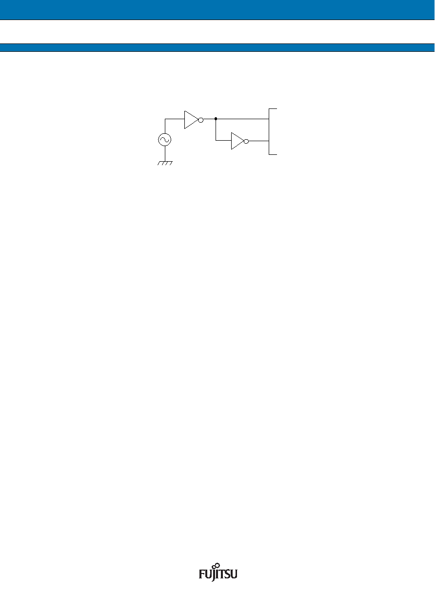
2. Opposite phase external clock
When using an opposite phase external clock, X1 (X1A) must be supplied with a clock signal which has the
opposite phase to the X0 (X0A) pins.
4.
Unused sub clock signal
If the pins X0A and X1A are not connected to an oscillator, a pull-down resistor must be connected on the X0A
pin and the X1A pin must be left open.
5.
Notes on PLL clock mode operation
If the PLL clock mode is selected and no external oscillator is operating or no external clock is supplied, the
microcontroller attempts to work with the free oscillating PLL. Performance of this operation, however, cannot
be guaranteed.
6.
Power supply pins (VCC/VSS)
It is required that all VCC-level as well as all VSS-level power supply pins are at the same potential. If there is more
than one VCC or VSS level, the device may operate incorrectly or be damaged even within the guaranteed operating
range.
VCC and VSS must be connected to the device from the power supply with lowest possible impedance.
As a measure against power supply noise, it is required to connect a bypass capacitor of about 0.1
F between
VCC and VSS as close as possible to VCC and VSS pins.
7.
Crystal oscillator and ceramic resonator circuit
Noise at X0, X1 pins or X0A, X1A pins might cause abnormal operation. It is required to provide bypass capacitors
with shortest possible distance to X0, X1 pins and X0A, X1A pins, crystal oscillator (or ceramic resonator) and
ground lines, and, to the utmost effort, that the lines of oscillation circuit do not cross the lines of other circuits.
It is highly recommended to provide a printed circuit board art work surrounding X0, X1 pins and X0A, X1A pins
with a ground area for stabilizing the operation.
It is highly recommended to evaluate the quartz/MCU or resonator/MCU system at the quartz or resonator
manufacturer, especially when using low-Q resonators at higher frequencies.
8.
Turn on sequence of power supply to A/D converter and analog inputs
It is required to turn the A/D converter power supply (AVCC, AVRH, AVRL) and analog inputs (ANn) on after
turning the digital power supply (VCC) on.
It is also required to turn the digital power off after turning the A/D converter supply and analog inputs off. In this
case, the voltage must not exceed AVRH or AVCC (turning the analog and digital power supplies simultaneously
on or off is acceptable).
9.
Pin handling when not using the A/D converter
It is required to connect the unused pins of the A/D converter as AVCC = VCC
, AVSS = AVRH = AVRL = VSS.
10. Notes on Power-on
To prevent malfunction of the internal voltage regulator, supply voltage prole while turning the power supply on
should be slower than 50
s from 0.2 V to 2.7 V.
X0
X1
相關(guān)PDF資料 |
PDF描述 |
|---|---|
| MB9AF131KPMC | 32-BIT, FLASH, RISC MICROCONTROLLER, PQFP48 |
| MB9AF131LPMC | 32-BIT, FLASH, RISC MICROCONTROLLER, PQFP64 |
| MB9AF132KPMC | 32-BIT, FLASH, RISC MICROCONTROLLER, PQFP48 |
| MB9AF131LPMC1 | 32-BIT, FLASH, RISC MICROCONTROLLER, PQFP64 |
| MB9BF116SPMC | 32-BIT, FLASH, RISC MICROCONTROLLER, PQFP144 |
相關(guān)代理商/技術(shù)參數(shù) |
參數(shù)描述 |
|---|---|
| MB96F395YWA | 制造商:FUJITSU 制造商全稱:Fujitsu Component Limited. 功能描述:16-bit Proprietary Microcontroller |
| MB96F395YWBPMC-GSE2 | 制造商:FUJITSU 制造商全稱:Fujitsu Component Limited. 功能描述:16-bit Proprietary Microcontroller |
| MB96F622ABPMC1-GSE2 | 制造商:FUJITSU 功能描述: |
| MB96F625RAPMC1-ESE1 | 制造商:FUJITSU 功能描述: |
| MB96F625RBPMC1-ESE2 | 制造商:FUJITSU 功能描述: |
發(fā)布緊急采購,3分鐘左右您將得到回復(fù)。