- 您現(xiàn)在的位置:買(mǎi)賣IC網(wǎng) > PDF目錄371003 > MC10E197FN (MOTOROLA INC) DATA SEPARATOR PDF資料下載
參數(shù)資料
| 型號(hào): | MC10E197FN |
| 廠商: | MOTOROLA INC |
| 元件分類: | 光電元器件 |
| 英文描述: | DATA SEPARATOR |
| 中文描述: | PULSE DETECTOR, PQCC28 |
| 封裝: | PLASTIC, LCC-28 |
| 文件頁(yè)數(shù): | 5/16頁(yè) |
| 文件大小: | 217K |
| 代理商: | MC10E197FN |
第1頁(yè)第2頁(yè)第3頁(yè)第4頁(yè)當(dāng)前第5頁(yè)第6頁(yè)第7頁(yè)第8頁(yè)第9頁(yè)第10頁(yè)第11頁(yè)第12頁(yè)第13頁(yè)第14頁(yè)第15頁(yè)第16頁(yè)

MC10E197
2–5
MOTOROLA
ECLinPS and ECLinPS Lite
DL140 — Rev 4
Idle Mode
In the absence of data or when the drive is writing to the disk,
PLL servoing is accomplished by pulling the read enable line
(RDEN) low and providing a reference clock via the REFCLK
pins. The condition whereby RDEN is low selects the
Phase/Frequency detector (Figure 1) and the 10E197 is said
to be operating in the “idle mode”. In order to function as a
frequency detector the input waveform must be periodic. The
pump up and pump down pulses from the Phase/Frequency
detector will have the same frequency, phase and pulse width
only when the two clocks that are being compared have their
positive edges aligned and are of the same frequency.
As with the data phase detector, by using suitable external
filter circuitry, a VCO input control signal can be generated by
inverting the pump down signal, summing the inverted signal
with the pump up signal and averaging the result. The polarity
of this control signal is defined as zero when all positive edges
of both clocks are coincident. For the case in which the
frequencies of the two clocks are the same but the clock edges
of the reference clock are slightly advanced with respect to the
VCO clock, the control clock is defined to have a positive
polarity. A control signal with negative polarity occurs when
the edges of the reference clock are delayed with respect to
those of the VCO. If the frequencies of the two clocks are
different, the clock with the most edges per unit time will initiate
the most pulses and the polarity of the detector will reflect the
frequency error. Thus, when the reference clock is high in
frequency than the VCO clock the polarity of the control signal
is positive; whereas a control signal with negative polarity
occurs when the frequency of the reference clock is lower than
the VCO clock.
Phase-Lock Loop Theory
Introduction
Phase lock loop (PLL) circuits are fundamentally feedback
systems used to synchronize the frequency of an oscillator to
an incoming signal. In addition to frequency synchronization,
the PLL circuitry is designed to minimize the phase difference
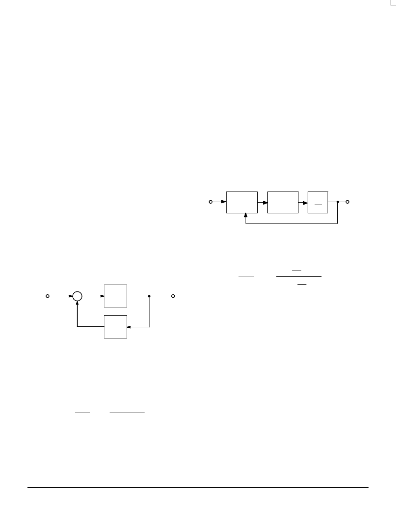
between the system input and output signals. A block diagram
of a feedback control system is shown in Figure 1.
where:
A(s) is the product of the feed-forward transfer functions.
Figure 1. Feedback System
Xi(s)
Xo(s)
A(s)
β
(s)
+
–
Xe(s)
R
β
(s) is the product of the feedback transfer functions.
The transfer function for this closed loop system is
Xo(s)
Xi(s)
=
A(s)
1 + A(s)
β
(s)
Typically, phase lock loops are modeled as feedback
systems connected in a unity feedback configuration (
β
(s)=1)
with a phase detector, a VCO (voltage controlled oscillator),
and a loop filter in the feed-forward path, A(s). Figure 2
illustrates a phase lock loop as a feedback control system in
block diagram form.
LOOP FILTER
F(s)
Fi
Fo
PHASE
DETECTOR
Kf
VCO
Ko
s
Figure 2. Phase Lock Loop Block Diagram
The closed loop transfer function is:
Xo(s)
Xi(s)
=
K
φ
Ko
s
F(s)
Ko
s
1 + K
φ
F(s)
where:
K
φ
=
Ko=
the phase detector gain.
the VCO gain. Since the VCO introduces a
pole at the origin of the s-plane, Ko is divided
by s.
F(s) = the transfer function of the loop filter.
The 10E197 is designed to implement the phase detector
and VCO functions in a unity feedback loop, while allowing the
user to select the desired filter function.
Gain Constants
As mentioned, each of the three sections in the phase lock
loop block diagram has an associated open loop gain
constant. Further, the gain constant of the filter circuitry is
composed of the product of three gain constants, one for each
filter subsection. The open loop gain constant of the
feed-forward path is given by
Kol = K
φ
* Ko * K1 * Kl * Kd
and obtained by performing a root locus analysis.
eqt. 1
Phase Detector Gain Constant
The gain of the phase detector is a function of the operating
mode and the data pattern. The 10E197 provides data
相關(guān)PDF資料 |
PDF描述 |
|---|---|
| MC10E197 | DATA SEPARATOR |
| MC10EL32D | Dual 1A Current-Limited, Power-Distribution Switches 8-MSOP-PowerPAD -40 to 85 |
| MC10EL32 | Dual 1A Current-Limited, Power-Distribution Switches 8-SOIC -40 to 85 |
| MC100EL32D | ±2 Divider |
| MC10EL33D | ±4 Divider |
相關(guān)代理商/技術(shù)參數(shù) |
參數(shù)描述 |
|---|---|
| MC10E211 C14N WAF | 制造商:ON Semiconductor 功能描述: |
| MC10E211FN | 功能描述:時(shí)鐘驅(qū)動(dòng)器及分配 5V ECL 1:6 Diff RoHS:否 制造商:Micrel 乘法/除法因子:1:4 輸出類型:Differential 最大輸出頻率:4.2 GHz 電源電壓-最大: 電源電壓-最小:5 V 最大工作溫度:+ 85 C 封裝 / 箱體:SOIC-8 封裝:Reel |
| MC10E211FNG | 功能描述:時(shí)鐘驅(qū)動(dòng)器及分配 5V ECL 1:6 Diff Clock Driver RoHS:否 制造商:Micrel 乘法/除法因子:1:4 輸出類型:Differential 最大輸出頻率:4.2 GHz 電源電壓-最大: 電源電壓-最小:5 V 最大工作溫度:+ 85 C 封裝 / 箱體:SOIC-8 封裝:Reel |
| MC10E211FNR2 | 功能描述:時(shí)鐘驅(qū)動(dòng)器及分配 5V ECL 1:6 Diff RoHS:否 制造商:Micrel 乘法/除法因子:1:4 輸出類型:Differential 最大輸出頻率:4.2 GHz 電源電壓-最大: 電源電壓-最小:5 V 最大工作溫度:+ 85 C 封裝 / 箱體:SOIC-8 封裝:Reel |
| MC10E211FNR2G | 功能描述:時(shí)鐘驅(qū)動(dòng)器及分配 5V ECL 1:6 Diff Clock Driver RoHS:否 制造商:Micrel 乘法/除法因子:1:4 輸出類型:Differential 最大輸出頻率:4.2 GHz 電源電壓-最大: 電源電壓-最小:5 V 最大工作溫度:+ 85 C 封裝 / 箱體:SOIC-8 封裝:Reel |
發(fā)布緊急采購(gòu),3分鐘左右您將得到回復(fù)。