- 您現(xiàn)在的位置:買賣IC網(wǎng) > PDF目錄371003 > MC10E197FN (MOTOROLA INC) DATA SEPARATOR PDF資料下載
參數(shù)資料
| 型號(hào): | MC10E197FN |
| 廠商: | MOTOROLA INC |
| 元件分類: | 光電元器件 |
| 英文描述: | DATA SEPARATOR |
| 中文描述: | PULSE DETECTOR, PQCC28 |
| 封裝: | PLASTIC, LCC-28 |
| 文件頁數(shù): | 7/16頁 |
| 文件大小: | 217K |
| 代理商: | MC10E197FN |

MC10E197
2–7
MOTOROLA
ECLinPS and ECLinPS Lite
DL140 — Rev 4
VOLTAGE
DIVIDER
FO(s)
AUGMENTNG
INTEGRATOR
FI(s)
FILTER
INPUT
F1(s)
Fi(s)
F(s)=F1(s)Fi(s)Fd(s)
Figure 4. Loop Filter Block Diagram
A root locus analysis is performed on the open loop transfer
function to determine the final pole-zero locations and the
open loop gain constant for the phase lock loop. Note that the
open loop gain constant impacts the crossover frequency and
that a lower frequency crossover point means a much more
efficient filter. Once these positions and constants are
determined the component values may be calculated.
IPUMPUP
IPUMPDN
VEEVCO
VEEVCO
VEEVCO
VEEVCO
VCCVCO
R1
R1
R1
R1
CIN
V01
MC34182
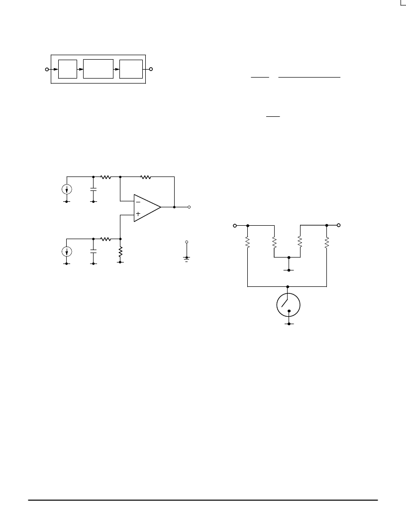
Figure 5. Filter Input Sunsection
Filter Input
The primary function of the filter input subsection is to
convert the output of the phase detector into a single ended
signal for subsequent processing by the integrator circuitry.
This subsection consists of the 10E197 charge pump current
sinks, two shunt capacitors, and a differential summing
amplifier (Figure 5).
Hence, this portion of the filter circuit contributes a real pole
and two complex poles to the overall loop transfer function
F(s). Before these pole locations are selected, appropriate
values for the current setting resistors (RSETUP and
RSETDN) must be ascertained. The goal in choosing these
resistor values is to maximize the gain of the filter input
subsection while ensuring the charge pump output transistors
operate in the active mode. The filter input gain is maximized
for a charge pump current of 1.1mA; a value of 464
for both
RSETUP and RSETDN yields a nominal charge pump current
of 1.1mA.
It should be noted that a dual bandwidth implementation
of the phase lock loop may be achieved by modifying the
current setting resistors such that an electronic switch
enables one of two resistor configurations. Figure 6 shows
a circuit configuration capable of providing this dual
bandwidth function. Analysis of the filter input circuitry yields
the transfer function:
F1(s) = K1 *
1
(s + p1)
*
1
where:
The gain constant is defined as:
K1 = A1 *
1
CIN
eqt. 3
A1= op-amp gain constant for the
selected pole positions.
CIN = phase detector shunt capacitor.
[s2 + (2
ζω
o1
ω
2 ]
The real pole is a function of the input resistance to the
op-amp and the shunt capacitors connected to the phase
detector output. For stability the real pole must be placed
beyond the unity gain frequency; hence, this pole is typically
placed midway between the unity crossover and phase
detector sampling frequency, which should be about ten
times greater.
ELECTRONIC SWITCH
VEEVCO
VEEVCO
RSETUP
RSETDN
464
464
464
464
Figure 6. Dual Bandwidth Current
Source Implementation
The second order pole set arises from the two pole model
for an op-amp. The open loop gain and the first open loop pole
for the op-amp are obtained from the data sheets. Typically,
op-amp manufacturers do not provide information on the
location of the second open loop pole; however, it can be
approximated by measuring the roll off of the op-amp in the
open loop configuration. The second pole is located where the
gain begins to decrease at a rate of 40dB per decade. The
inclusion of both poles in the differential summing amplifier
transfer function becomes important when closing the
feedback path around the op-amp because the poles migrate;
and this migration must be accounted for to accurately
determine the phase lock loop transient performance.
Typically the op-amp poles can be approximated by a pole
pair occurring as a complex conjugate pair making an angle
of 45
°
to the real axis of the complex frequency plane. Two
constraints on the selection of the op-amp pole pair are that
相關(guān)PDF資料 |
PDF描述 |
|---|---|
| MC10E197 | DATA SEPARATOR |
| MC10EL32D | Dual 1A Current-Limited, Power-Distribution Switches 8-MSOP-PowerPAD -40 to 85 |
| MC10EL32 | Dual 1A Current-Limited, Power-Distribution Switches 8-SOIC -40 to 85 |
| MC100EL32D | ±2 Divider |
| MC10EL33D | ±4 Divider |
相關(guān)代理商/技術(shù)參數(shù) |
參數(shù)描述 |
|---|---|
| MC10E211 C14N WAF | 制造商:ON Semiconductor 功能描述: |
| MC10E211FN | 功能描述:時(shí)鐘驅(qū)動(dòng)器及分配 5V ECL 1:6 Diff RoHS:否 制造商:Micrel 乘法/除法因子:1:4 輸出類型:Differential 最大輸出頻率:4.2 GHz 電源電壓-最大: 電源電壓-最小:5 V 最大工作溫度:+ 85 C 封裝 / 箱體:SOIC-8 封裝:Reel |
| MC10E211FNG | 功能描述:時(shí)鐘驅(qū)動(dòng)器及分配 5V ECL 1:6 Diff Clock Driver RoHS:否 制造商:Micrel 乘法/除法因子:1:4 輸出類型:Differential 最大輸出頻率:4.2 GHz 電源電壓-最大: 電源電壓-最小:5 V 最大工作溫度:+ 85 C 封裝 / 箱體:SOIC-8 封裝:Reel |
| MC10E211FNR2 | 功能描述:時(shí)鐘驅(qū)動(dòng)器及分配 5V ECL 1:6 Diff RoHS:否 制造商:Micrel 乘法/除法因子:1:4 輸出類型:Differential 最大輸出頻率:4.2 GHz 電源電壓-最大: 電源電壓-最小:5 V 最大工作溫度:+ 85 C 封裝 / 箱體:SOIC-8 封裝:Reel |
| MC10E211FNR2G | 功能描述:時(shí)鐘驅(qū)動(dòng)器及分配 5V ECL 1:6 Diff Clock Driver RoHS:否 制造商:Micrel 乘法/除法因子:1:4 輸出類型:Differential 最大輸出頻率:4.2 GHz 電源電壓-最大: 電源電壓-最小:5 V 最大工作溫度:+ 85 C 封裝 / 箱體:SOIC-8 封裝:Reel |
發(fā)布緊急采購,3分鐘左右您將得到回復(fù)。