- 您現(xiàn)在的位置:買(mǎi)賣(mài)IC網(wǎng) > PDF目錄371008 > MC13122 (Motorola, Inc.) AMAX STEREO IC CHIPSET PDF資料下載
參數(shù)資料
| 型號(hào): | MC13122 |
| 廠(chǎng)商: | Motorola, Inc. |
| 英文描述: | AMAX STEREO IC CHIPSET |
| 中文描述: | 中宇立體聲IC芯片組 |
| 文件頁(yè)數(shù): | 21/28頁(yè) |
| 文件大?。?/td> | 586K |
| 代理商: | MC13122 |
第1頁(yè)第2頁(yè)第3頁(yè)第4頁(yè)第5頁(yè)第6頁(yè)第7頁(yè)第8頁(yè)第9頁(yè)第10頁(yè)第11頁(yè)第12頁(yè)第13頁(yè)第14頁(yè)第15頁(yè)第16頁(yè)第17頁(yè)第18頁(yè)第19頁(yè)第20頁(yè)當(dāng)前第21頁(yè)第22頁(yè)第23頁(yè)第24頁(yè)第25頁(yè)第26頁(yè)第27頁(yè)第28頁(yè)

MC13027 MC13122
21
MOTOROLA ANALOG IC DEVICE DATA
60
4.0
S
RF INPUT LEVEL (dB
μ
V)
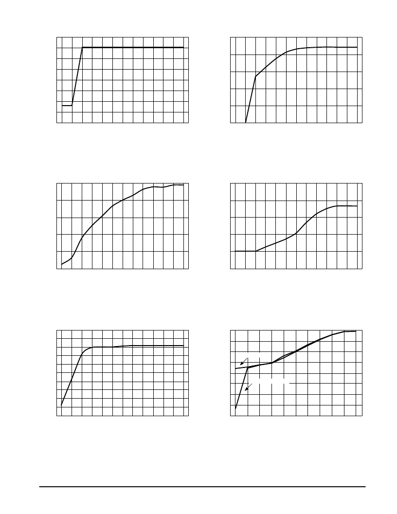
This measurement was made on the MC13122 alone
with a 10 k series input resistor. It will enable the
designer to determine the stop–sense level if the gain
of receiver RF section is known. Note that if Pin 23 is
held low, the SS voltage on Pin 6 rises from about 0.3
to 2.2 V over a small change in RF level. This can be
used to generate a very reliable stop signal. If Pin 23 is
not held low, the SS voltage starts out at 2.2 V and
rises slowly to a maximum of around 4.0 V.
3.0
2.0
1.0
0
70
80
90
100
110
20
500
A
ANTENNA INPUT (dB
μ
V)
All the curves of performance versus RF input level
were generated using the car radio receiver circuit
shown in Figure 6. Using a 15/60 pF dummy antenna
input and a 50% L only stereo signal.
400
300
200
100
0
30
40
50
60
70
80
20
0
5
ANTENNA INPUT (dB
μ
V)
This curve shows the effect of the variable audio
bandwidth control of the MC13122. It is due to the
variable loading of the IF coil and the variable 10 kHz
notch filter in the output.
–5.0
–10
–15
–20
–25
30
40
50
60
70
80
20
50
4
ANTENNA INPUT (dB
μ
V)
The slightly abrupt change at around 25 dB
μ
V is due
to the decoder switching into stereo.
42
34
26
18
10
30
40
50
60
70
80
20
40
S
ANTENNA INPUT (dB
μ
V)
The radio stays in mono until the stereo signal is
sufficiently large and then makes a smooth transition to
stereo. This is similar to FM receivers with variable
blend.
30
40
50
60
70
80
32
24
16
8.0
0
20
4.0
B
ANTENNA INPUT (dB
μ
V)
The graphs on this page were made using the 15/60 pF
dummy antenna and the Application Circuit of Figure 6.
30
40
50
60
70
80
3.0
2.0
1.0
0
Figure 10. Blend Voltage versus RF Input Level
Figure 11. Separation versus RF Input Level
Figure 12. Signal to Noise versus RF Input Level
Figure 13. 5.0 kHz Attentuation
versus RF Input Level
Figure 14. Audio Output Level
versus RF Input Level
Figure 15. Stop–Sense Voltage
versus RF Input Level
NOTE:
NOTE:
NOTE:
NOTE:
NOTE:
NOTE:
Pin 23 = Open
Pin 23 = Grounded
相關(guān)PDF資料 |
PDF描述 |
|---|---|
| MC13027DW | AMAX STEREO IC CHIPSET |
| MC13027P | AMAX STEREO IC CHIPSET |
| MC13122P | CONNECTOR KIT, JPS130PT; RoHS Compliant: Yes |
| MC13135DW | DUAL CONVERSION NARROWBAND FM RECEIVERS |
| MC13136 | DUAL CONVERSION NARROWBAND FM RECEIVERS |
相關(guān)代理商/技術(shù)參數(shù) |
參數(shù)描述 |
|---|---|
| MC13122DW | 制造商:MOTOROLA 制造商全稱(chēng):Motorola, Inc 功能描述:AMAX STEREO IC CHIPSET |
| MC13122P | 制造商:MOTOROLA 制造商全稱(chēng):Motorola, Inc 功能描述:AMAX STEREO IC CHIPSET |
| MC1312P | 制造商:MOTOROLA 制造商全稱(chēng):Motorola, Inc 功能描述:CBS SQ LOGIC DECODER SYSTEM |
| MC13135 | 制造商:MOTOROLA 制造商全稱(chēng):Motorola, Inc 功能描述:DUAL CONVERSION NARROWBAND FM RECEIVERS |
| MC13135DW | 制造商:MOTOROLA 制造商全稱(chēng):Motorola, Inc 功能描述:DUAL CONVERSION NARROWBAND FM RECEIVERS |
發(fā)布緊急采購(gòu),3分鐘左右您將得到回復(fù)。