- 您現(xiàn)在的位置:買賣IC網(wǎng) > PDF目錄377963 > MD1210 (Supertex, Inc.) HIGH SPEED DUAL MOSFET DRIVER PDF資料下載
參數(shù)資料
| 型號: | MD1210 |
| 廠商: | Supertex, Inc. |
| 英文描述: | HIGH SPEED DUAL MOSFET DRIVER |
| 中文描述: | 高速雙MOSFET驅(qū)動器 |
| 文件頁數(shù): | 2/5頁 |
| 文件大小: | 178K |
| 代理商: | MD1210 |
MD1210
NR013105
2
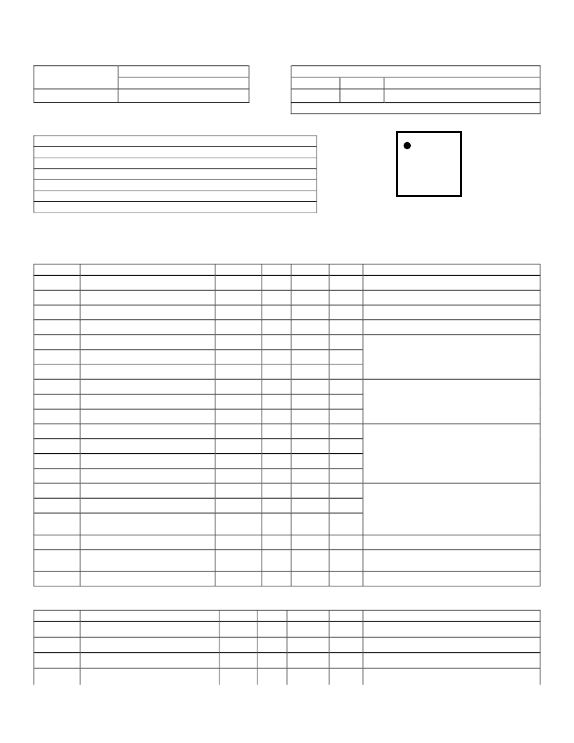
Ordering Information
Package Option
12-lead 4x4x0.9 QFN
MD1210K6
Product Marking Information
1210
YWLL
Year, Week Code, Lot Number
Example: 5A88 means Lot #88 of first or second week in 2005
Device
1
st
line
2
nd
line
Device Number
MD1210
Absolute Maximum Ratings*
V
DD
-V
SS
, Logic Supply Voltage
V
H
, Output High Supply Voltage
V
L
, Output Low Supply Voltage
V
SS
, Low Side Supply Voltage
Logic Input Levels
Maximum Junction Temperature
Storage Temperature
*Absolute Maximum Ratings are those values beyond which damage to the device may occur. Functional
operation under these conditions is not implied. Continuous operation of the device at the absolute rating
level may affect device reliability. All voltages are referenced to device ground.
Pin1
→
DC Electrical Characteristics
(Over operating conditions unless otherwise specified, V
H
=V
DD
1=V
DD
2=12V, V
L
=V
SS
1=V
SS
2=0V, V
OE
=3.3V, T
J
= 25°C)
Sym
Parameter
Min
V
DD
-V
SS
Logic supply voltage
4.5
V
SS
Low side supply voltage
-5.5
V
H
Output high supply voltage
V
SS
+2.0
V
L
Output low supply voltage
V
SS
I
DD1Q
V
DD1
quiescent current
I
DD2Q
V
DD2
quiescent current
I
HQ
V
H
quiescent current
I
DD1
V
DD1
average current
I
DD2
V
DD2
average current
I
H
V
H
average current
V
IH
Input logic voltage high
V
OE
-0.3
V
IL
Input logic voltage low
I
IH
Input logic current high
I
IL
Input logic current low
V
IH
OE Input logic voltage high
1.2
V
IL
OE Input logic voltage low
Input logic impedance to
GND
C
IN
Logic input capacitance
Typ
0.55
0.88
6.6
23
Max
13
0
V
DD
V
DD
-2
10
10
5.0
0.3
1.0
1.0
5.0
0.3
Units
V
V
V
V
mA
μA
μA
mA
mA
mA
V
V
μA
μA
V
V
Conditions
No input transitions
One channel on at 5.0Mhz, No load
0
For logic inputs INA and INB.
0
R
IN
12
20
30
K
For logic input OE
5.0
10
pF
All Inputs
1oz. 4-layer 3x4inch PCB with thermal
pad and thermal via array.
°C/W
θ
JA
Thermal resistance to air
47
°C/W
θ
JC
Outputs
(V
H
=V
DD
1=V
DD
2=12V, V
L
=V
SS
1=V
SS
2=0V, V
OE
=3.3V, T
J
=25°C)
Sym
Parameter
R
SINK
Output sink resistance
R
SOURCE
Output source resistance
I
SINK
Peak output sink current
I
SOURCE
Peak output source current
Thermal resistance to case
7.0
Min
Typ
2.0
Max
12.5
12.5
Units
A
Conditions
I
SINK
=50mA
I
SOURCE
=50mA
2.0
A
-0.5V to +13.5V
V
L
-0.5V to V
DD
+0.5V
V
SS
-0.5V to V
H
+0.5V
-7.0V to +0.5V
V
SS
-0.5V to V
SS
+7.0V
+125°C
-65°C to 150°C
1210
YWLL
Top View
相關(guān)PDF資料 |
PDF描述 |
|---|---|
| MD1210K6 | HIGH SPEED DUAL MOSFET DRIVER |
| MD1320N | 3.3V/5V Stepping Down DC to DC Converter Power IC |
| MD1332F | High-Efficiency Step Down DC-DC Converter Power Integrated Circuit |
| MD1620F | 5V Stepping Down DC to DC Converter Power IC |
| MD1711 | HIGH SPEED INTEGRATED ULTRASOUND DRIVER IC |
相關(guān)代理商/技術(shù)參數(shù) |
參數(shù)描述 |
|---|---|
| MD1210_07 | 制造商:SUPERTEX 制造商全稱:SUPERTEX 功能描述:High Speed Dual MOSFET Driver |
| MD121-0001-0608 | 制造商: 功能描述: 制造商:undefined 功能描述: |
| MD121-0002-0322 | 制造商: 功能描述: |
| MD121-0002-0422 | 制造商: 功能描述: 制造商:undefined 功能描述: |
| MD121-0002-0813 | 制造商: 功能描述: |
發(fā)布緊急采購,3分鐘左右您將得到回復(fù)。