- 您現(xiàn)在的位置:買賣IC網(wǎng) > PDF目錄383612 > MIC5013BN (MICREL INC) FPGA 1000000 SYSTEM GATE 1.8 VOLT - NOT RECOMMENDED for NEW DESIGN PDF資料下載
參數(shù)資料
| 型號(hào): | MIC5013BN |
| 廠商: | MICREL INC |
| 元件分類: | 功率晶體管 |
| 英文描述: | FPGA 1000000 SYSTEM GATE 1.8 VOLT - NOT RECOMMENDED for NEW DESIGN |
| 中文描述: | BUF OR INV BASED MOSFET DRIVER, PDIP8 |
| 封裝: | PLASTIC, DIP-8 |
| 文件頁數(shù): | 11/16頁 |
| 文件大?。?/td> | 153K |
| 代理商: | MIC5013BN |
July 2000
11
MIC5013
MIC5013
Applications Information
(Continued)
Micrel
Fault
V+
Gate
1
2
3
4
8
MIC5013
Input
Gnd
7
6
5
Thresh
Sense
Source
IRFP250
100μF
6.2k
Figure 10. High-Voltage
Bootstrapped Driver
+
10m
KC1000-4T
(Kelvin)
1N4003
90V
100k
1k
100k
4N35
33k
33pF
MPSA05
10mA
Control Input
M
15V
1N4003 (2)
15Vp-p, 20kHz
Squarewave
1N4746
100nF
200V
1/4 HP, 90V
5BPB56HAA100
(GE)
Since the supply current in the
“
OFF
”
state is only a small
leakage, the 100nF bypass capacitor tends to remain
charged for several seconds after the MIC5013 is turned off.
In a PWM application the chip supply is actually much
higher than the system supply, which improves switching
time.
Electronic Circuit Breaker
(Figure 7). The MIC5013 forms
the basis of a high-performance, fast-acting circuit breaker.
By adding feedback from FAULT to INPUT the breaker can
be made to automatically reset. If an over-current condition
occurs, the circuit breaker shuts off. The breaker tests the
load every 18ms until the short is removed, at which time the
circuit latches ON. No reset button is necessary.
Opto-Isolated Interface
(Figure 8). Although the MIC5013
has no special input slew rate requirement, the lethargic
transitions provided by an opto-isolator may cause oscilla-
tions on the rise and fall of the output. The circuit shown
accelerates the input transitions from a 4N35 opto-isolator
by adding hysteresis. Opto-isolators are used where the
control circuitry cannot share a common ground with the
MIC5013 and high-current power supply, or where the
control circuitry is located remotely. This implementation is
intrinsically safe; if the control line is severed the MIC5013
will turn OFF.
Fault-Protected Industrial Switch
(Figure 9). The most
common manual control for industrial loads is a push button
on/off switch. The
“
on
”
button is physically arranged in a
recess so that in a panic situation the
“
off
”
button, which
extends out from the control box, is more easily pressed.
This circuit is compatible with control boxes such as the
CR2943 series (GE). The circuit is configured so that if both
switches close simultaneously, the
“
off
”
button has prece-
dence. If there is a fault condition the circuit will latch off, and
it can be reset by pushing the
“
ON
”
button.
This application also illustrates how two (or more) MOSFETs
can be paralleled. This reduces the switch drop, and distrib-
utes the switch dissipation into multiple packages.
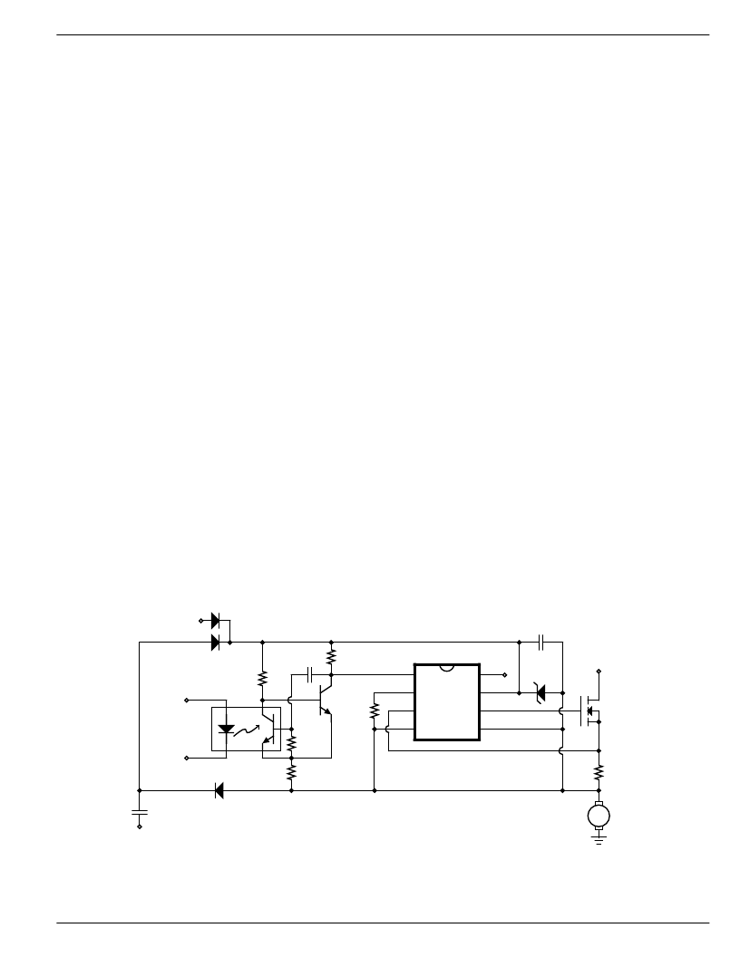
High-Voltage Bootstrap
(Figure 10). Although the MIC5013
is limited to operation on 7 to 32V supplies, a floating
bootstrap arrangement can be used to build a high-side
switch that operates on much higher voltages. The MIC5013
and MOSFET are configured as a low-side driver, but the
load is connected in series with ground. The high speed
normally associated with low-side drivers is retained in this
circuit.
Power for the MIC5013 is supplied by a charge pump. A
20kHz square wave (15Vp-p) drives the pump capacitor
and delivers current to a 100
μ
F storage capacitor. A zener
diode limits the supply to 18V. When the MIC5013 is off,
power is supplied by a diode connected to a 15V supply.
The circuit of Figure 8 is put to good use as a barrier
between low voltage control circuitry and the 90V motor
supply.
Half-Bridge Motor Driver
(Figure 11). Closed loop control
of motor speed requires a half-bridge driver. This topology
presents an extra challenge since the two output devices
should not cross conduct (shoot-through) when switching.
Cross conduction increases output device power dissipa-
tion and, in the case of the MIC5013, could trip the over-
current comparator. Speed is also important, since PWM
control requires the outputs to switch in the 2 to 20kHz
range.
The circuit of Figure 11 utilizes fast configurations for both
the top- and bottom-side drivers. Delay networks at each
input provide a 2 to 3
μ
s dead time effectively eliminating
cross conduction. Both the top- and bottom-side drivers are
protected, so the output can be shorted to either rail without
damage.
相關(guān)PDF資料 |
PDF描述 |
|---|---|
| MIC5020 | Replaced by PTN78060W : |
| MIC5020BM | Replaced by PTN78060W : |
| MIC5020BN | Replaced by PTN78060W : |
| MIC5021 | Replaced by PTN78060W : |
| MIC5021BM | Replaced by PTN78060W : |
相關(guān)代理商/技術(shù)參數(shù) |
參數(shù)描述 |
|---|---|
| MIC5013YM | 功能描述:功率驅(qū)動(dòng)器IC High Side MOSFET Predriver - Lead Free RoHS:否 制造商:Micrel 產(chǎn)品:MOSFET Gate Drivers 類型:Low Cost High or Low Side MOSFET Driver 上升時(shí)間: 下降時(shí)間: 電源電壓-最大:30 V 電源電壓-最小:2.75 V 電源電流: 最大功率耗散: 最大工作溫度:+ 85 C 安裝風(fēng)格:SMD/SMT 封裝 / 箱體:SOIC-8 封裝:Tube |
| MIC5013YM TR | 功能描述:功率驅(qū)動(dòng)器IC High Side MOSFET Predriver - Lead Free RoHS:否 制造商:Micrel 產(chǎn)品:MOSFET Gate Drivers 類型:Low Cost High or Low Side MOSFET Driver 上升時(shí)間: 下降時(shí)間: 電源電壓-最大:30 V 電源電壓-最小:2.75 V 電源電流: 最大功率耗散: 最大工作溫度:+ 85 C 安裝風(fēng)格:SMD/SMT 封裝 / 箱體:SOIC-8 封裝:Tube |
| MIC5013YN | 功能描述:功率驅(qū)動(dòng)器IC High Side MOSFET Predriver - Lead Free RoHS:否 制造商:Micrel 產(chǎn)品:MOSFET Gate Drivers 類型:Low Cost High or Low Side MOSFET Driver 上升時(shí)間: 下降時(shí)間: 電源電壓-最大:30 V 電源電壓-最小:2.75 V 電源電流: 最大功率耗散: 最大工作溫度:+ 85 C 安裝風(fēng)格:SMD/SMT 封裝 / 箱體:SOIC-8 封裝:Tube |
| MIC5014 | 制造商:MICREL 制造商全稱:Micrel Semiconductor 功能描述:Low-Cost High- or Low-Side MOSFET Driver |
| MIC5014_05 | 制造商:MICREL 制造商全稱:Micrel Semiconductor 功能描述:Low-Cost High- or Low-Side MOSFET Driver |
發(fā)布緊急采購,3分鐘左右您將得到回復(fù)。