- 您現(xiàn)在的位置:買賣IC網(wǎng) > PDF目錄359168 > MK41T56S00TR (意法半導(dǎo)體) 512 bit 64b x8 Serial Access TIMEKEEPER SRAM PDF資料下載
參數(shù)資料
| 型號(hào): | MK41T56S00TR |
| 廠商: | 意法半導(dǎo)體 |
| 英文描述: | 512 bit 64b x8 Serial Access TIMEKEEPER SRAM |
| 中文描述: | 512位64B條x8串行SRAM的訪問(wèn)計(jì)時(shí)器 |
| 文件頁(yè)數(shù): | 6/15頁(yè) |
| 文件大小: | 102K |
| 代理商: | MK41T56S00TR |
第1頁(yè)第2頁(yè)第3頁(yè)第4頁(yè)第5頁(yè)當(dāng)前第6頁(yè)第7頁(yè)第8頁(yè)第9頁(yè)第10頁(yè)第11頁(yè)第12頁(yè)第13頁(yè)第14頁(yè)第15頁(yè)
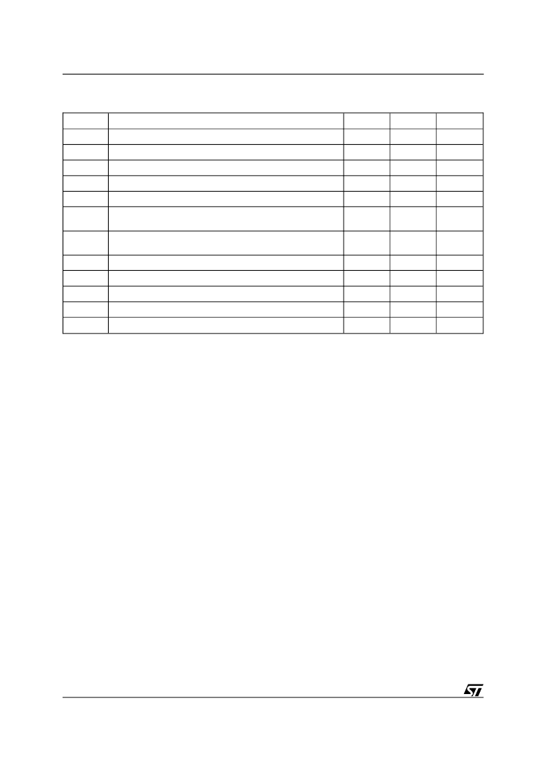
Symbol
Parameter
Min
Max
Unit
f
SCL
SCL Clock Frequency
0
100
kHz
t
LOW
Clock Low Period
4.7
μ
s
t
HIGH
Clock High Period
4
μ
s
t
R
SDA and SCL Rise Time
1
μ
s
t
F
SDA and SCL Fall Time
300
ns
t
HD:STA
START Condition Hold Time
(after this period the first clock pulse is generated)
4
μ
s
t
SU:STA
START Condition Setup Time
(only relevant for a repeated start condition)
4.7
μ
s
t
SU:DAT (1)
Data Setup Time
250
ns
t
HD:DAT
Data Hold Time
0
μ
s
t
SU:STO
STOP Condition Setup Time
4.7
μ
s
t
BUF
Time the bus must be free before a new transmission can start
4.7
μ
s
t
I
Noise suppression time constant at SCL and SDA input
0.25
1
μ
s
Note:
1. Transmitter must internally provide a hold time to bridge the undefined region (300ns max.) of the falling edge of SCL.
Table 10. AC Characteristics
(T
A
= 0 to 70
°
C or –40 to 85
°
C; V
CC
= 4.5V to 5.5V)
Accordingly, the following bus conditions have
been defined:
Bus not busy.
Both data and clock lines remain
High.
Start data transfer.
A change in the state of the
data line, from High to Low, while the clock is High,
defines the START condition.
Stop data transfer.
A change in the state of the
data line, from Low to High, while the clock is High,
defines the STOP condition.
Data valid.
The state of the data line represents
valid data when after a start condition, the data line
is stable for the duration of the High period of the
clock signal. The data on the line may be changed
during the Low period of the clock signal. There is
one clock pulse per bit of data.
Each data transfer is initiated with a start condition
and terminated with a stop condition. The number
of data bytes transferred between the start and stop
conditions is not limited. The information is trans-
mitted byte-wide and each receiver acknowledges
with a ninth bit.
By definition, a device that gives out a message is
called "transmitter", the receiving device that gets
the message is called "receiver". The device that
controls the message is called "master". The de-
vices that are controlled by the master are called
"slaves".
Acknowledge.
Each byte of eight bits is followed
by one acknowledge bit. This acknowledge bit is a
low level put on the bus by the receiver, whereas
the master generates an extra acknowledge re-
lated clock pulse.
A slave receiver which is addressed is obliged to
generate an acknowledge after the reception of
each byte. Also, a master receiver must generate
an acknowledge after the reception of each byte
that has been clocked out of the slave transmitter.
The device that acknowledges has to pull down the
SDA line during the acknowledge clock pulse in
such a way that the SDA line is a stable Low during
the High period of the acknowledge related clock
pulse. Of course, setup and hold times must be
taken into account. A master receiver must signal
an end-of-data to the slave transmitter by not gen-
erating an acknowledge on the last byte that has
been clocked out of the slave. In this case, the
transmitter must leave the data line High to enable
the master to generate the STOP condition.
2-WIRE BUS CHARACTERISTICS
(cont’d)
6/15
MK41T56, MKI41T56
相關(guān)PDF資料 |
PDF描述 |
|---|---|
| MK41T56S00 | 512 bit 64b x8 Serial Access TIMEKEEPER SRAM |
| MK45H03K | VERY FAST CMOS 512/1K/2K x9BiPORT FIFO |
| MK45H03N | VERY FAST CMOS 512/1K/2K x9BiPORT FIFO |
| MK45H03 | VERY FAST CMOS 512/1K/2K x9BiPORT FIFO |
| MK48Z02 | FILTER SAW BNDPASS 43.75MHZ 5SIP |
相關(guān)代理商/技術(shù)參數(shù) |
參數(shù)描述 |
|---|---|
| MK4200 | 制造商:Abus 功能描述:Bulk |
| MK4222F | 制造商:Ohmite Mfg Co 功能描述: |
| MK424BS | 制造商:POP 功能描述: |
| MK4321F | 制造商:Ohmite Mfg Co 功能描述:Res Metal Film 4.32K Ohm 1% 1/4W ±50ppm/°C Conformal AXL Thru-Hole Ammo Pack |
| MK43A232-008 | 制造商:TE Connectivity 功能描述: |
發(fā)布緊急采購(gòu),3分鐘左右您將得到回復(fù)。