- 您現(xiàn)在的位置:買賣IC網(wǎng) > PDF目錄383645 > MT9075 (Mitel Networks Corporation) () PDF資料下載
參數(shù)資料
| 型號: | MT9075 |
| 廠商: | Mitel Networks Corporation |
| 英文描述: | () |
| 中文描述: | () |
| 文件頁數(shù): | 9/16頁 |
| 文件大?。?/td> | 95K |
| 代理商: | MT9075 |
Application Note
MSAN-174
9
The details on the microprocessor interface design
for Mitel digital switches can be found in [5] and [6].
3.4 Data link layer control
In the V5 interface, the 64Kb/s time slots on
2.048Mb/s links are assigned according to two types:
the B-channel and the C-channel. On each 2.048Mb/
s link there are, at most, 3 time slots, namely 15, 16
and 31, that can be used as physical C-channel. The
C-channel is dedicated for carrying the following
information types which are subject to the high data
link control (HDLC) protocol:
the layer 2 data link carrying the control
protocol;
the layer 2 data link carrying the PSTN
signaling;
the layer 2 data link carrying the link control
signaling (for V5.2 only);
the layer 2 data link carrying the BCC signaling
(for V5.2 only);
each of the layer 2 data links carrying the
protection protocol (for V.5.2 only);
all the ISDN Ds-data from one or more user
ports;
all the ISDN p-data from one or more user
ports;
all the ISDN f-data from one or more user ports.
3.4.1 Time slot Allocation for physical
communication channels
When a single 2.048 Mbps link is used in the V5.2
interface then the allocation should be identical to
the
V5.1
recommendations
compatibility with V5.1.
to
ensure
full
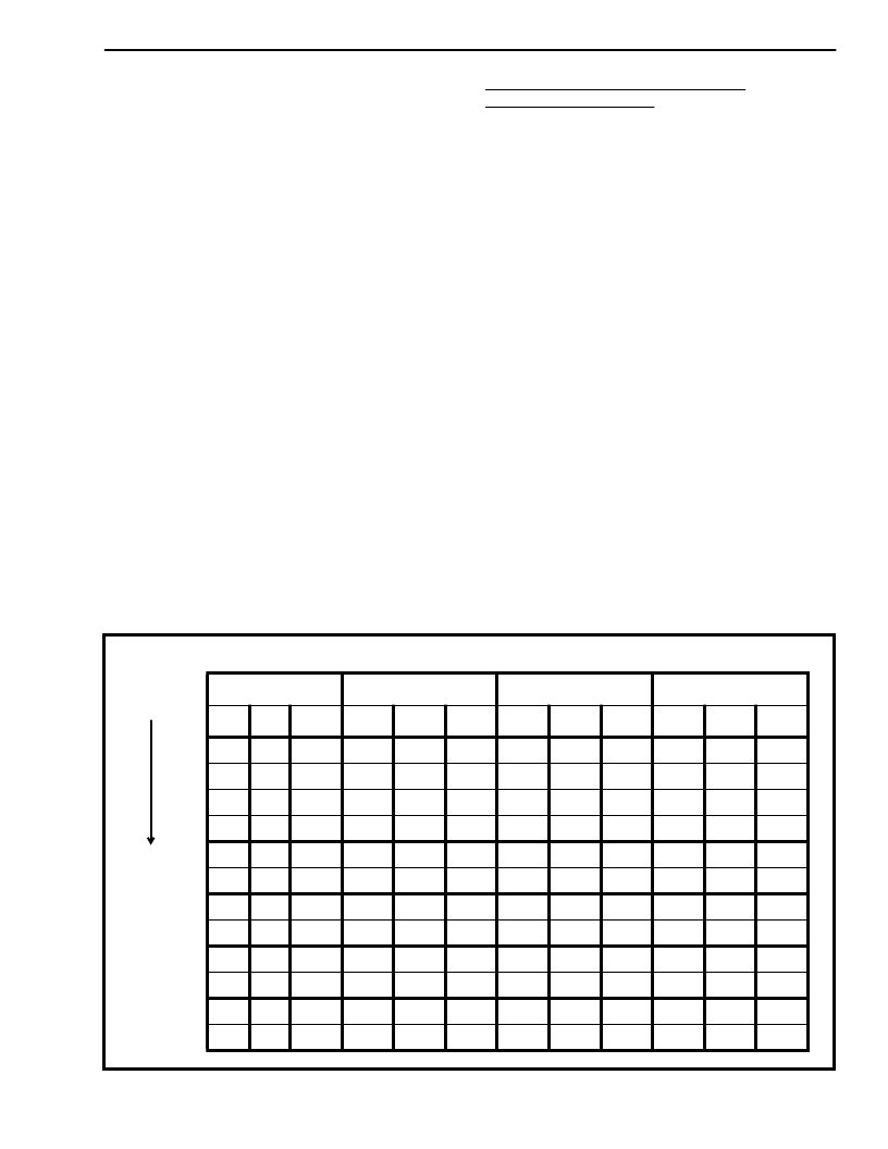
The underlying principle for allocation of physical
time slots in the case of multiple E1 links is to
minimize the number of links with an odd number of
bearer channels. This process will simplify assigning
ISDN ports onto the E1 links. Timeslot 16 of all the
links should be used first followed by timeslots 15
and 31. Table 2 shows an illustration of the physical
timeslot allocation for four E1 links.
The HDLC protocol structures and formats the data
as per Q.921 recommendation of the ITU. It provides
the zero insertion and deletion for data transparency,
generates and detects flags, recognizes address
bytes, and provides a cyclic redundancy check on
data packets.
Although three physical C-channels have been
reserved for each 2.048Mb/s link, implying a
maximum demand for 48 HDLC controllers in V5.2
interface, the actual needs of HDLC resources in real
applications could be much less because the PSTN
protocol must be contained in one single logical C-
channel. The number of physical C channels
Table 2 - Sequence of Allocation of Physical Communication Time Slots
Primary Link
Secondary Link
Link 3
Link 4
15
16
31
15
16
31
15
16
31
15
16
31
X
X
X
X
X
X
X
X
X
X
X
X
X
X
X
X
X
X
X
X
X
X
X
X
X
X
X
X
X
X
X
X
X
X
X
X
X
X
X
X
X
X
X
X
X
X
X
X
X
X
X
X
X
X
X
X
X
X
X
X
X
X
X
X
X
X
X
X
X
X
X
X
X
X
X
X
X
X
Allocation
Sequence
相關(guān)PDF資料 |
PDF描述 |
|---|---|
| MT9076 | T1/E1/J1 3.3V Single Chip Transceiver |
| MT9076AB | T1/E1/J1 3.3V Single Chip Transceiver |
| MT9076 | T1/E1/J1 3.3V Single Chip Transceiver(T1/E1/J1 3.3V 單片收發(fā)器) |
| MT9079 | Advanced Controller for E1(先進的E1幀調(diào)節(jié)器和控制器) |
| MT9080B | SMX - Switch Matrix Module(用于消費類轉(zhuǎn)換應(yīng)用的開關(guān)矩陣模塊) |
相關(guān)代理商/技術(shù)參數(shù) |
參數(shù)描述 |
|---|---|
| MT9075A | 制造商:MITEL 制造商全稱:Mitel Networks Corporation 功能描述:E1 Single Chip Transceiver |
| MT9075AL | 制造商:MITEL 制造商全稱:Mitel Networks Corporation 功能描述:E1 Single Chip Transceiver |
| MT9075AP | 制造商:MITEL 制造商全稱:Mitel Networks Corporation 功能描述:E1 Single Chip Transceiver |
| MT9075B | 制造商:ZARLINK 制造商全稱:Zarlink Semiconductor Inc 功能描述:E1 Single Chip Transceiver |
| MT9075B-1 | 制造商:MITEL 制造商全稱:Mitel Networks Corporation 功能描述:E1 Single Chip Transceiver |
發(fā)布緊急采購,3分鐘左右您將得到回復(fù)。