- 您現(xiàn)在的位置:買賣IC網(wǎng) > PDF目錄383645 > MT9092 (Mitel Networks Corporation) Digital Telephone with HDLC(數(shù)字電話(帶高階數(shù)據(jù)鏈路控制HDLC)) PDF資料下載
參數(shù)資料
| 型號(hào): | MT9092 |
| 廠商: | Mitel Networks Corporation |
| 英文描述: | Digital Telephone with HDLC(數(shù)字電話(帶高階數(shù)據(jù)鏈路控制HDLC)) |
| 中文描述: | 數(shù)字電話(數(shù)字電話(帶高階數(shù)據(jù)鏈路控制的HDLC)與的HDLC) |
| 文件頁數(shù): | 15/44頁 |
| 文件大?。?/td> | 278K |
| 代理商: | MT9092 |
第1頁第2頁第3頁第4頁第5頁第6頁第7頁第8頁第9頁第10頁第11頁第12頁第13頁第14頁當(dāng)前第15頁第16頁第17頁第18頁第19頁第20頁第21頁第22頁第23頁第24頁第25頁第26頁第27頁第28頁第29頁第30頁第31頁第32頁第33頁第34頁第35頁第36頁第37頁第38頁第39頁第40頁第41頁第42頁第43頁第44頁
MT9092
7-17
Transducer Interfaces
Four standard telephony transducer interfaces are
provided by the HPhone-
II
. These are:
±
The handset microphone inputs (transmitter),
pins M+/M- and the speakerphone microphone
inputs, pins MIC+/MIC-. The transmit path is
muted/not-muted by the MIC EN control bit.
Selection of which input pair is to be routed to
the transmit filter amplifier is acomplished by the
MIC/HNSTMIC control bit. Both of these reside
in the Transducer Control Register (address
0Eh). The nominal transmit path gain may be
adjusted to either 6.1dB (suggested for
μ
-Law)
or 15.4dB (suggested for A-Law). Control of this
gain is provided by the MICA/u control bit
(General Control Register, address 0Fh). This
gain
adjustment
is
programmable gain provided by the transmit
filter and DSP.
in
addition
to
the
±
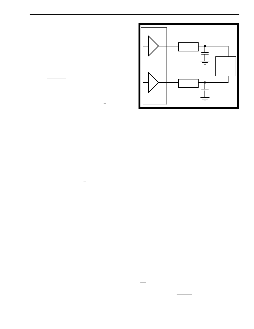
The handset speaker outputs (receiver), pins
HSPKR+/HSPKR-.
compensated, fully differential output driver is
capable of driving the load shown in Figure 5.
This output is enabled/disabled by the HSSPKR
EN bit residing in the Transducer Control
Register (address 0Eh). The nominal handset
receive path gain may be adjusted to either
-12.3dB (suggested for
(suggested for A-Law). Control of this gain is
provided by the RxA/u control bit (General
Control Register, address 0Fh). This gain
adjustment is in addition to the programmable
gain provided by the receive filter and DSP.
This
internally
μ
-Law) or -9.7dB
±
The loudspeaker outputs, pins SPKR+/SPKR-.
This internally compensated, fully differential
output driver is capable of directly driving 6.5vpp
into a 40 ohm load. This output is enabled/
disabled by the SPKR EN bit residing in the
Transducer Control Register (address 0Eh). The
nominal gain for this amplifier is 0.2dB.
C-Channel
Access to the internal control and status registers of
Mitel basic rate, layer 1, transceivers is through the
ST-BUS Control Channel (C-Channel), since direct
microport access is not usually provided, except in
the case of the SNIC (MT8930). The HPhone-
II
provides asynchronous microport access to the ST-
BUS C-Channel information on both DSTo and DSTi
via a double-buffered read/write register (address
14h). Data written to this address is transmitted on
the C-Channel every frame when enabled by CH
1
EN
(see ST-BUS/Timing Control).
Figure 5- Handset Speaker Driver
LCD
A twelve segment, non-multiplexed, LCD display
controller is provided for easy implementation of
various set status and call progress indicators. The
twelve output pins (S
n
) are used in conjunction with
12 segment control bits, located in LCD Segment
Enable Registers 1&2 (addresses 12h and 13h), and
the BackPlane output pin (BP) to control the on/off
state of each segment individually.
The BP pin drives a continuous 62.5Hz, 50% duty
cycle squarewave output signal. An individual
segment is controlled via the phase relationship of its
segment driver output pin with respect to the
backplane, or common, driver output. Each of the
twelve Segment Enable bits corresponds to a
segment output pin. The waveform at each segment
pin is in-phase with the BP waveform when its
control bit is set to logic zero (segment off) and is
out-of-phase with the BP waveform when its control
bit is set to a logic high (segment on). Refer to the
LCD
Driver
Characteristics
information.
for
pin
loading
Microport
A serial microport, compatible with Intel MCS-51
(mode 0) specifications, provides access to all
HPhone-
II
internal read and write registers. This
microport consists of three pins; a half-duplex
transmit/receive data pin (DATA1), a chip select pin
(CS) and a synchronous data clock pin (SCLK).
On power-up reset (PWRST) or with a software reset
(RST), the DATA1 pin becomes a bidirectional
(transmit/receive) serial port while the DATA2 pin is
internally disconnected and tri-stated.
HSPKR+
HSPKR-
75
75
1000 pF
150 ohm
load
(speaker)
1000 pF
ground
MT9092
相關(guān)PDF資料 |
PDF描述 |
|---|---|
| MT9092 | ISO2-CMOS ST-BUS⑩ FAMILY Digital Telephone with HDLC (HPhone-II) |
| MT9094 | Digital Telephone (DPhone-II)(數(shù)字電話) |
| MT9122 | Dual Voice Echo Canceller with Tone Detection(雙話音回聲消除器(帶音調(diào)檢測功能)) |
| MT9122AE | CMOS Dual Voice Echo Canceller with Tone Detection |
| MT9122AP | CMOS Dual Voice Echo Canceller with Tone Detection |
相關(guān)代理商/技術(shù)參數(shù) |
參數(shù)描述 |
|---|---|
| MT9092AP | 制造商:Microsemi Corporation 功能描述: |
| MT9092AP1 | 制造商:Zarlink Semiconductor Inc 功能描述:DGTL TEL 44PLCC - Rail/Tube 制造商:Zarlink Semiconductor Inc 功能描述:PB FREE H-PHONE-PLUS PLCC |
| MT9092APR | 制造商:Microsemi Corporation 功能描述:DGTL TEL 44PLCC - Tape and Reel |
| MT9092APR1 | 制造商:Microsemi Corporation 功能描述:DGTL TEL 44PLCC - Tape and Reel 制造商:MICROSEMI CONSUMER MEDICAL PRODUCT GROUP 功能描述:IC DGTL TELEPHONE CIRCUIT 44PLCC 制造商:Microsemi Corporation 功能描述:IC DGTL TELEPHONE CIRCUIT 44PLCC |
| MT9094 | 制造商:MITEL 制造商全稱:Mitel Networks Corporation 功能描述:ISO2-CMOS ST-BUS⑩ FAMILY Digital Telephone (DPhone-II) |
發(fā)布緊急采購,3分鐘左右您將得到回復(fù)。