- 您現(xiàn)在的位置:買賣IC網(wǎng) > PDF目錄367627 > P2500AA61RP MCU CMOS 80 LD 33MHZ 8K EPRM, 0C to +70C, 80-TQFP, TRAY PDF資料下載
參數(shù)資料
| 型號: | P2500AA61RP |
| 英文描述: | MCU CMOS 80 LD 33MHZ 8K EPRM, 0C to +70C, 80-TQFP, TRAY |
| 中文描述: | SIDAC的| 290V五(公報)最大| 800mA的我(縣)|對220VAR |
| 文件頁數(shù): | 82/161頁 |
| 文件大?。?/td> | 986K |
| 代理商: | P2500AA61RP |
第1頁第2頁第3頁第4頁第5頁第6頁第7頁第8頁第9頁第10頁第11頁第12頁第13頁第14頁第15頁第16頁第17頁第18頁第19頁第20頁第21頁第22頁第23頁第24頁第25頁第26頁第27頁第28頁第29頁第30頁第31頁第32頁第33頁第34頁第35頁第36頁第37頁第38頁第39頁第40頁第41頁第42頁第43頁第44頁第45頁第46頁第47頁第48頁第49頁第50頁第51頁第52頁第53頁第54頁第55頁第56頁第57頁第58頁第59頁第60頁第61頁第62頁第63頁第64頁第65頁第66頁第67頁第68頁第69頁第70頁第71頁第72頁第73頁第74頁第75頁第76頁第77頁第78頁第79頁第80頁第81頁當(dāng)前第82頁第83頁第84頁第85頁第86頁第87頁第88頁第89頁第90頁第91頁第92頁第93頁第94頁第95頁第96頁第97頁第98頁第99頁第100頁第101頁第102頁第103頁第104頁第105頁第106頁第107頁第108頁第109頁第110頁第111頁第112頁第113頁第114頁第115頁第116頁第117頁第118頁第119頁第120頁第121頁第122頁第123頁第124頁第125頁第126頁第127頁第128頁第129頁第130頁第131頁第132頁第133頁第134頁第135頁第136頁第137頁第138頁第139頁第140頁第141頁第142頁第143頁第144頁第145頁第146頁第147頁第148頁第149頁第150頁第151頁第152頁第153頁第154頁第155頁第156頁第157頁第158頁第159頁第160頁第161頁

GR 1089-Core
SIDACtor
Data Book
4 - 8
Teccor Electronics
(972) 580-7777
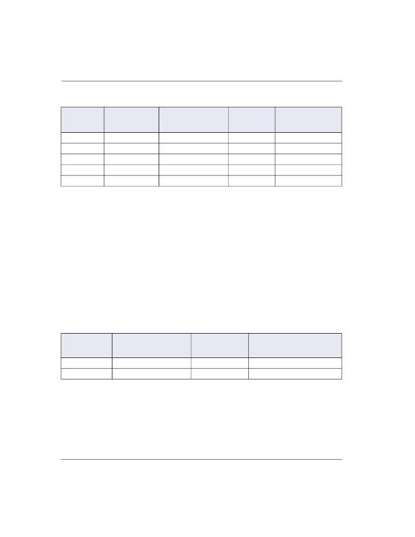
Table 4-5 Second Level AC Power Fault Test for Non-Customer Premises Equipment
Short Circuit Current
per Conductor
(A)
5
1
120, 277
25
Notes:
1. Primary protectors are removed for all tests.
2. For EUT containing secondary voltage limiting and current limiting protectors, tests are to be
performed at the indicated voltage(s) and repeated at a reduced voltage and current just below the
operating threshold of the secondary protectors.
3. This test is to be performed between the ranges of 100V-600V and is intended to produce the
greatest heating affect.
4. Test 5 simulates a high impedance induction fault. Specific information regarding this test is
available upon request.
5. These tests are repeated using a short-circuit value just below the operating threshold of the
current limiting device or if the EUT uses a fuse as current limiting protection, the fuse may be
bypassed and the short circuit current available adjusted to 135% of the fuse rating.
Second Level AC Power Fault for Customer Premises Equipment
For customer premises equipment, the EUT is tested to the conditions shown in Table
4-6 and connected to a circuit equivalent to Figure 4-2. During this test, the wiring
simulator can not open. For equipment that uses premises type of wiring, the wiring
simulator is a 1.6A Type MDQ fuse from Bussman. For equipment that is connected
via cable, the wiring simulator is a piece of 26 gauge copper wire.
Table 4-6 Second Level AC Power Fault for Customer Premises Equipment
Notes:
1. Applied between exposed surfaces and ground.
2. The 60Hz signal is applied with an initial amplitude of 30V
RMS
and 30mA and increased by 20%
every 15 minutes until:
a.The voltage reaches the maximum specified.
b.The current reaches 20A or the wiring simulator opens.
c.The EUT fails open circuit.
3. If the EUT fails open circuit, the test will continue for an additional 15 minutes to ensure that
another component of the EUT does not create a fire, fragmentation, or electrical safety hazard.
Test
(Note 1, 2)
Applied Voltage,
60Hz
(V
RMS
)
Duration
Test Connections
(Table 4-1, Fig. 4-1)
15 minutes
A
2
600
60
5 seconds
A
3
600
7
5 seconds
A
4 (Note 3)
100-600
2.2A at 600V
15 minutes
A
5 (Note 4)
N/A
N/A
15 minutes
N/A
Test
Applied Voltage, 60Hz
(V
RMS
)
Source
Impedance
20
Test Connections
(Table 4-1, Fig. 4-2)
1
300
(Note 1)
2
600
20
A
相關(guān)PDF資料 |
PDF描述 |
|---|---|
| P2600EA | MCU CMOS 28 LD 40MHZ 8K OTP, -40C to +125C, 28-SPDIP, TUBE |
| P2600EARP1 | MCU CMOS 28 LD 40MHZ 8K OTP, -40C to +85C, 28-SPDIP, TUBE |
| P2702AA | MCU CMOS 84 LD LOW PWR, -40C to +85C, 84-PLCC, TUBE |
| P2702AARP | SIDAC|160V V(BO) MAX|800MA I(S)|TO-220VAR |
| P2702AB | SIDAC|160V V(BO) MAX|800MA I(S)|TO-220VAR |
相關(guān)代理商/技術(shù)參數(shù) |
參數(shù)描述 |
|---|---|
| P2500ATL | 制造商:SEMIKRON 制造商全稱:Semikron International 功能描述:Standard silicon rectifier diodes |
| P2500B | 制造商:SEMIKRON 制造商全稱:Semikron International 功能描述:Standard silicon rectifier diodes |
| P2500BTL | 制造商:SEMIKRON 制造商全稱:Semikron International 功能描述:Standard silicon rectifier diodes |
| P2500D | 制造商:SEMIKRON 制造商全稱:Semikron International 功能描述:Standard silicon rectifier diodes |
| P2500DTL | 制造商:SEMIKRON 制造商全稱:Semikron International 功能描述:Standard silicon rectifier diodes |
發(fā)布緊急采購,3分鐘左右您將得到回復(fù)。