- 您現(xiàn)在的位置:買賣IC網(wǎng) > PDF目錄367813 > PCD6001 (NXP Semiconductors N.V.) Digital telephone answering machine chip PDF資料下載
參數(shù)資料
| 型號(hào): | PCD6001 |
| 廠商: | NXP Semiconductors N.V. |
| 英文描述: | Digital telephone answering machine chip |
| 中文描述: | 數(shù)字電話應(yīng)答機(jī)芯片 |
| 文件頁(yè)數(shù): | 75/96頁(yè) |
| 文件大小: | 385K |
| 代理商: | PCD6001 |
第1頁(yè)第2頁(yè)第3頁(yè)第4頁(yè)第5頁(yè)第6頁(yè)第7頁(yè)第8頁(yè)第9頁(yè)第10頁(yè)第11頁(yè)第12頁(yè)第13頁(yè)第14頁(yè)第15頁(yè)第16頁(yè)第17頁(yè)第18頁(yè)第19頁(yè)第20頁(yè)第21頁(yè)第22頁(yè)第23頁(yè)第24頁(yè)第25頁(yè)第26頁(yè)第27頁(yè)第28頁(yè)第29頁(yè)第30頁(yè)第31頁(yè)第32頁(yè)第33頁(yè)第34頁(yè)第35頁(yè)第36頁(yè)第37頁(yè)第38頁(yè)第39頁(yè)第40頁(yè)第41頁(yè)第42頁(yè)第43頁(yè)第44頁(yè)第45頁(yè)第46頁(yè)第47頁(yè)第48頁(yè)第49頁(yè)第50頁(yè)第51頁(yè)第52頁(yè)第53頁(yè)第54頁(yè)第55頁(yè)第56頁(yè)第57頁(yè)第58頁(yè)第59頁(yè)第60頁(yè)第61頁(yè)第62頁(yè)第63頁(yè)第64頁(yè)第65頁(yè)第66頁(yè)第67頁(yè)第68頁(yè)第69頁(yè)第70頁(yè)第71頁(yè)第72頁(yè)第73頁(yè)第74頁(yè)當(dāng)前第75頁(yè)第76頁(yè)第77頁(yè)第78頁(yè)第79頁(yè)第80頁(yè)第81頁(yè)第82頁(yè)第83頁(yè)第84頁(yè)第85頁(yè)第86頁(yè)第87頁(yè)第88頁(yè)第89頁(yè)第90頁(yè)第91頁(yè)第92頁(yè)第93頁(yè)第94頁(yè)第95頁(yè)第96頁(yè)

2001 Apr 17
75
Philips Semiconductors
Product specification
Digital telephone answering machine chip
PCD6001
16.2.3
P
ORT
4 R
EGISTER
(P4)
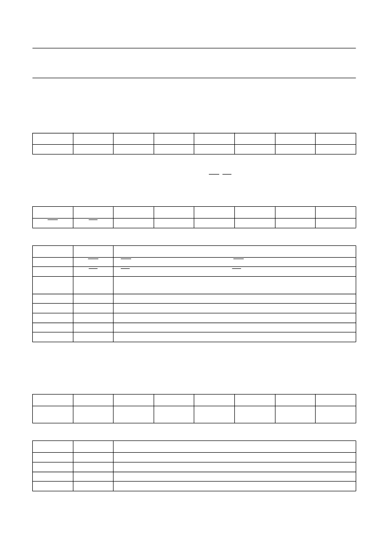
The alternative outputs (GPC, FSO, FSK and LE) are connected with the general purpose outputs via an AND gate.
Therefore, when using the alternative functions the corresponding port bits should be set to a logic 1.
Table 73
Port 4 Register (SFR address 98H); bit addressable; reset state 1EHH; note 1
16.2.4
P
ORT
4 C
ONFIGURATION
R
EGISTER
(P4CFG)
This register is used to select the output configuration of the pins WR, RD and P4.0 to P4.4. The output configuration is
open-drain by default after reset. Note that the output configuration of P4.5 is selected by the P4.5 bit in SFR ALTP.
Table 74
Port 4 Configuration Register (SFR address 9FH); reset state 00H
Table 75
Description of P4CFG bits
16.2.5
A
LTERNATIVE
P
ORT
F
UNCTION
R
EGISTER
(ALTP)
This register selects the pin configuration for the MSK, IOM master/slave and general purpose function; see Table 77.
The general purpose clock function is described in Section 9.1. The LE functionality is described in Section 10.13.
Table 76
Alternative Port Function Register (SFR address ABH); reset state 00H
Table 77
P3.7, P3.6, P3.1 and P3.0 selection of pin configurations for alternative function
7
6
5
4
3
2
1
0
P4.5/GPC
P4.4/FSI
P4.3
P4.2/FSO
P4.1/FSK
P4.0/LE
7
6
5
4
3
2
1
0
WR
RD
EAM
P4.4
P4.3
P4.2
P4.1
P4.0
BIT
SYMBOL
DESCRIPTION
7
6
5
WR
RD
EAM
If WR = 0, then open-drain configuration. If WR = 1, then push-pull configuration.
If RD = 0, then open-drain configuration. If RD = 1, then push-pull configuration.
The EAM bit is used to select the Enhanced Addressing Mode; this is described in more
detail in Chapter 12.
If P4.4 = 0, then open-drain configuration. If P4.4 = 1, then push-pull configuration.
If P4.3 = 0, then open-drain configuration. If P4.3 = 1, then push-pull configuration.
If P4.2 = 0, then open-drain configuration. If P4.2 = 1, then push-pull configuration.
If P4.1 = 0, then open-drain configuration. If P4.1 = 1, then push-pull configuration.
If P4.0 = 0, then open-drain configuration. If P4.0 = 1, then push-pull configuration.
4
3
2
1
0
P4.4
P4.3
P4.2
P4.1
P4.0
7
6
5
4
3
2
1
0
IOM on P3
IOM master/
MSK
P4.5
GPC off/on
GPC source
LE off/on
early LE
ALTP.6
ALTP.5
MODE
0
0
1
1
0
1
0
1
general purpose I/O port
MSK
IOM slave
IOM master
相關(guān)PDF資料 |
PDF描述 |
|---|---|
| PCD6001H | Digital telephone answering machine chip |
| PCD6001U | Digital telephone answering machine chip |
| PCD8582D-2P | 256 x 8-bit CMOS EEPROMS with I2C-bus interface |
| PCD8582D-2 | 256 x 8-bit CMOS EEPROMS with I2C-bus interface |
| PCD8582D-2T | 256 x 8-bit CMOS EEPROMS with I2C-bus interface |
相關(guān)代理商/技術(shù)參數(shù) |
參數(shù)描述 |
|---|---|
| PCD6001H | 制造商:PHILIPS 制造商全稱:NXP Semiconductors 功能描述:Digital telephone answering machine chip |
| PCD6001U | 制造商:PHILIPS 制造商全稱:NXP Semiconductors 功能描述:Digital telephone answering machine chip |
| PCD6002H/2 | 制造商:未知廠家 制造商全稱:未知廠家 功能描述:Solid-State Recorder |
| PCD6003 | 制造商:PHILIPS 制造商全稱:NXP Semiconductors 功能描述:Digital telephone answering machine chip |
| PCD6003H | 制造商:PHILIPS 制造商全稱:NXP Semiconductors 功能描述:Digital telephone answering machine chip |
發(fā)布緊急采購(gòu),3分鐘左右您將得到回復(fù)。