- 您現(xiàn)在的位置:買(mǎi)賣(mài)IC網(wǎng) > PDF目錄370003 > PIEZO_SYSTEMS_PRODUCT_CATALOG 600mA, 500kHz Step-Down Switching Regulator in SOT-23; Package: SOT; No of Pins: 6; Temperature Range: -40°C to +125°C PDF資料下載
參數(shù)資料
| 型號(hào): | PIEZO_SYSTEMS_PRODUCT_CATALOG |
| 英文描述: | 600mA, 500kHz Step-Down Switching Regulator in SOT-23; Package: SOT; No of Pins: 6; Temperature Range: -40°C to +125°C |
| 文件頁(yè)數(shù): | 47/52頁(yè) |
| 文件大小: | 643K |
| 代理商: | PIEZO_SYSTEMS_PRODUCT_CATALOG |
第1頁(yè)第2頁(yè)第3頁(yè)第4頁(yè)第5頁(yè)第6頁(yè)第7頁(yè)第8頁(yè)第9頁(yè)第10頁(yè)第11頁(yè)第12頁(yè)第13頁(yè)第14頁(yè)第15頁(yè)第16頁(yè)第17頁(yè)第18頁(yè)第19頁(yè)第20頁(yè)第21頁(yè)第22頁(yè)第23頁(yè)第24頁(yè)第25頁(yè)第26頁(yè)第27頁(yè)第28頁(yè)第29頁(yè)第30頁(yè)第31頁(yè)第32頁(yè)第33頁(yè)第34頁(yè)第35頁(yè)第36頁(yè)第37頁(yè)第38頁(yè)第39頁(yè)第40頁(yè)第41頁(yè)第42頁(yè)第43頁(yè)第44頁(yè)第45頁(yè)第46頁(yè)當(dāng)前第47頁(yè)第48頁(yè)第49頁(yè)第50頁(yè)第51頁(yè)第52頁(yè)

PIEZOCERAMIC
APPLICATIONDATA
P
IEZ O
S
Y ST EMS
, I
NC
.
186 Mssachusetts Avenue Cambridge, MA02139 Te: (617) 547-1777 Fax: (617) 354-2200 Web wwwpezocom E-mail: sales@pezocom
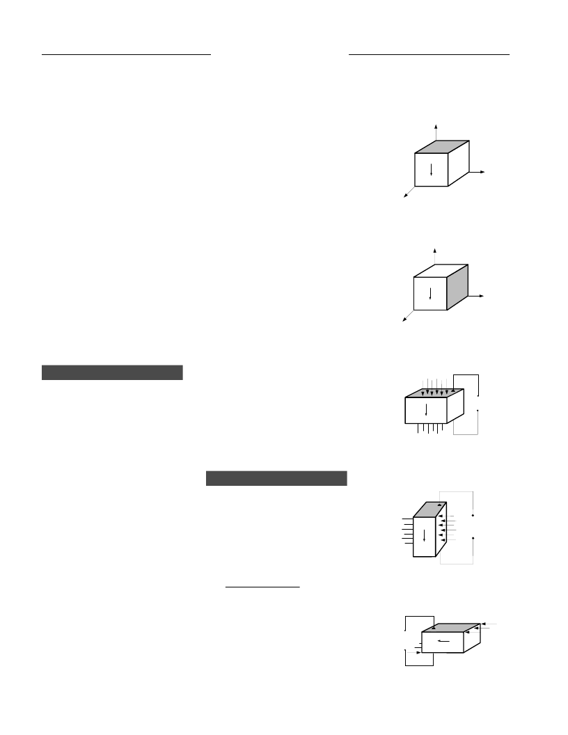
The piezoelectric constants relating
the mechanical strain produced by an
applied electric field are termed the
strain constants, or the “d” coeffi-
cients. The units may then be
expressed as meters per meter, per
volts per meter (meters per volt).
It is useful to remember that large d
ij
constants relate to large mechanical
displacements which are usually
sought in motional transducer
devices. Conversely, the coefficient
may be viewed as relating the charge
collected on the electrodes, to the
applied mechanical stress.d
33
applies
2
1
3
P
+
–
2
1
3
P
+
–
Q or V
F
–
+
P
+
–
Q or V
–
F
+
P
+
–
Q or V
–
F
+
P
+
–
Figure - 1a
Figure - 1b
Figure - 2a
Figure - 2b
Figure - 2c
When a piezoceramic element is
stressed electrically by a voltage, its
dimensions change.
stressed mechanically by a force, it
generates an electric charge. If the
electrodes are not short-circuited, a
voltage associated with the charge
appears.
When it is
A piezoceramic is therefore capable
of acting as either a sensing or trans-
mitting element,or both. Since piezo-
ceramic elements are capable of gen-
erating very high voltages, they are
compatible with today’s generation of
solid-state devices — rugged, com-
pact,reliable,and efficient.
The following text describes the ter-
minology of piezoceramics and the
relationship among variables for func-
tional applications.
Relationships between applied forces
and the resultant responses depend
upon: the piezoelectric properties of
the ceramic;the size and shape of the
piece;and the direction of the electri-
cal and mechanical excitation.
To identify directions in a piezoce-
ramic element, three axes are used.
These axes, termed 1, 2 and 3, are
analogous to X,Y and Z of the classi-
cal three dimensional orthogonal set
of axes (Figure 1a)
The polar or 3 axis is taken parallel to
the direction of polarization within
the ceramic. This direction is estab-
lished during manufacturing by a high
DC voltage that is applied between a
pair of electroded faces to activate
the material. The polarization vector
“P” is represented by an arrow point-
ing from the positive to the negative
poling electrode. In shear operations,
these poling electrodes are later
removed and replaced by electrodes
deposited on a second pair of faces.
In this event,the 3 axis is not altered,
but is then parallel to the electroded
RELATIONSHIPS
faces found on the finished element
(Figure 1b). When the mechanical
stress or strain is shear,the subscript
5 is used in the second place.
Piezoelectric coefficients with double
subscripts link electrical and mechan-
ical quantities.
The first subscript
gives the direction of the electrical
field associated with the voltage
applied,or the charge produced. The
second subscript gives the direction
of the mechanical stress or strain.
Several piezoceramic material con-
stants may be written with a “super-
script” which specifies either a
mechanical or electrical boundary
condition. The superscripts are T, E,
D and S,signifying:
T = constant stress
= mechanically free
E = constant field = short circuit
D = constant electrical displacement
= open circuit
S = constant strain
= mechanically clamped
As an example, K
T3
expresses the
relative dielectric constant (K), mea-
sured in the polar direction (3) with
no mechanical clamping applied.
"D" CONSTANT
d =
strain developed
applied electric field
IN T R
O D U C T IO N
T
T
O P IE Z O E L E C T R IC IT Y
47
CATALOG #3, 1998
相關(guān)PDF資料 |
PDF描述 |
|---|---|
| PIIPM15P12D007 | Programmable Isolated IPM |
| PIIPM25P12B008 | Programmable solated intelligent power module. a 25A. 1200V. three-phase inverter for 15kW industrial and servo motors with on-board programmable DSP. current sensing. isolation. gate drivers and power stage. |
| PIIPM50P12B004 | Programmable solated intelligent power module. a 50A. 1200V. three-phase inverter for 15kW industrial and servo motors with on-board programmable DSP. current sensing. isolation. gate drivers and power stage. |
| PIMM25SG144B | 500kHz and 1MHz High Efficiency 1.5A Switching Regulators; Package: SO; No of Pins: 8; Temperature Range: -40?°C to 85?°C |
| PIMM25SG144M | Microprocessor |
相關(guān)代理商/技術(shù)參數(shù) |
參數(shù)描述 |
|---|---|
| PIF 130 7/8 | 制造商:Belden Inc 功能描述:PVC COATED FIBERGLASS SLEEVIN |
| PIF130 4 250BLK | 制造商:61200 功能描述:WIRE/CABLE |
| PIF1300 BK005 | 功能描述:非熱縮管和套管 PROTECTION SLV 100ft SPOOL BLACK RoHS:否 制造商:Panduit 產(chǎn)品:Cable Wraps 類型:Spiral 顏色:Black 材料:PP 內(nèi)徑:0.03 in 長(zhǎng)度:100 ft |
| PIF-130-0-BK-100 | 制造商:Alpha Wire Company 功能描述:Cable Accessories Sleeve Polyvinyl Chloride Black |
| PIF1301/2A BK005 | 功能描述:非熱縮管和套管 1/2in PROTECTION SLV 100ft SPOOL BLACK RoHS:否 制造商:Panduit 產(chǎn)品:Cable Wraps 類型:Spiral 顏色:Black 材料:PP 內(nèi)徑:0.03 in 長(zhǎng)度:100 ft |
發(fā)布緊急采購(gòu),3分鐘左右您將得到回復(fù)。