- 您現(xiàn)在的位置:買賣IC網(wǎng) > PDF目錄368122 > PS20351-G (POWEREX INC) Intellimod⑩ Module Dual-In-Line Intelligent Power Module 3 Amperes/500 Volts PDF資料下載
參數(shù)資料
| 型號: | PS20351-G |
| 廠商: | POWEREX INC |
| 元件分類: | 運動控制電子 |
| 英文描述: | Intellimod⑩ Module Dual-In-Line Intelligent Power Module 3 Amperes/500 Volts |
| 中文描述: | AC MOTOR CONTROLLER, 6 A, UFM26 |
| 封裝: | POWER, MINI, DIP-26 |
| 文件頁數(shù): | 4/9頁 |
| 文件大小: | 183K |
| 代理商: | PS20351-G |
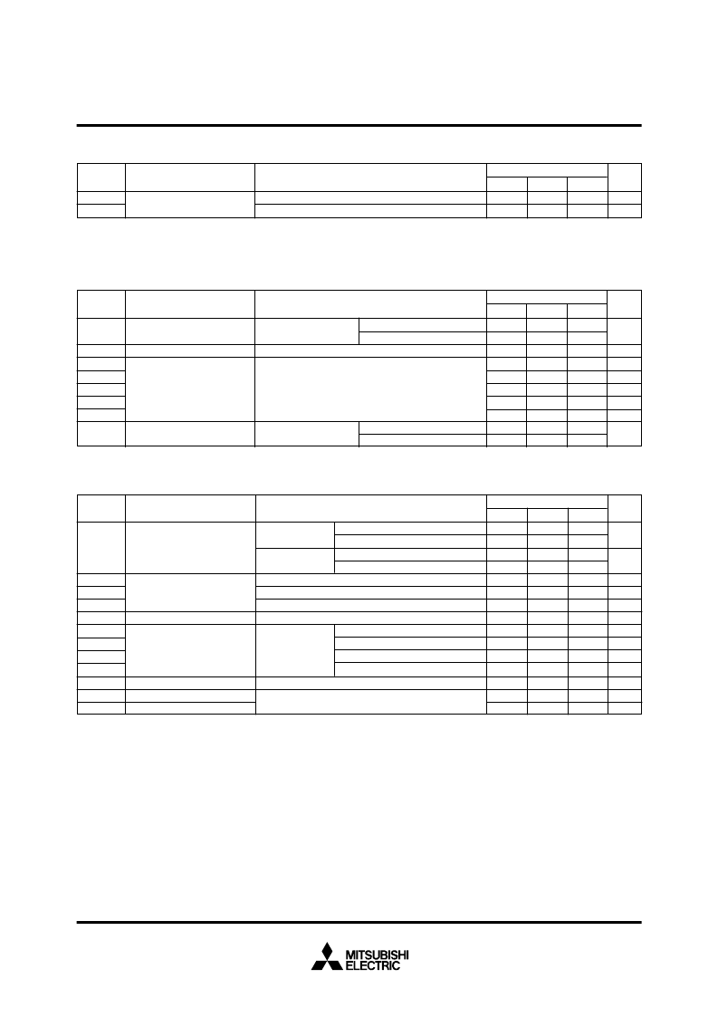
MITSUBISHI SEMICONDUCTOR <Intelligent Power Module>
PS20351-N
TRANSFER-MOLD TYPE
INSULATED TYPE
Sep. 2001
Condition
Symbol
Parameter
Limits
Typ.
—
—
Inverter IGBT part (per 1/6 module)
Inverter FWD part (per 1/6 module)
(Note 3)
(Note 3)
R
th(j-f)Q
R
th(j-f)F
Note 3:
Grease with good thermal conductivity should be applied evenly about +100
μ
m~+200
μ
m on the contact surface of a DIP-IPM and a
heat sink.
Min.
—
—
°
C/W
°
C/W
THERMAL RESISTANCE
Max.
7.0
8.0
Unit
Junction-to-heat sink thermal
resistance
2.35
2.45
2.6
1.35
—
0.60
1.35
0.95
1
10
mA
V
T
j
= 25
°
C
T
j
= 125
°
C
I
C
= 3A, T
j
= 25
°
C
I
C
= 3A, T
j
= 125
°
C
V
CE(sat)
V
EC
t
on
t
rr
t
c(on)
t
off
t
c(off)
I
CES
T
j
= 25
°
C,
–
I
C
= 5A, V
CIN
= 5V
V
CC
= 280V, V
D
= V
DB
=15V
I
C
= 3A, T
j
= 125
°
C
Inductive load (upper-lower arm)
V
CIN
= 5
0V
Condition
Symbol
Parameter
Limits
Typ.
1.7
1.8
1.9
0.9
0.25
0.35
0.90
0.45
—
—
Min.
—
—
—
0.4
—
—
—
—
—
—
Max.
Unit
ELECTRICAL CHARACTERISTICS
(T
j
= 25
°
C, unless otherwise noted)
INVERTER PART
Collector-emitter saturation
voltage
FWD forward voltage
V
D
= V
DB
= 15V
V
CIN
= 0V
Switching times
Collector-emitter cut-off
current
V
CE
= V
CES
V
μ
s
μ
s
μ
s
μ
s
μ
s
8.5
1.0
9.7
1.0
—
0.9
1.8
0.53
12.0
12.5
12.5
13.0
—
2.0
4.0
—
—
—
—
4.9
—
0.8
0.43
10.0
10.5
10.3
10.8
1.0
0.8
2.5
Note 4:
Short-circuit protection operates only at the low-arms. Please select the value of the external shunt resistor such that the SC trip level
is less than 5.1A
5:
Fault signal is outputted when the low-arm short-circuit or control supply under-voltage protective functions operate. The fault output
pulse-width t
FO
depends on the capacitance value of C
FO
according to the following approximate equation. : C
FO
= (12.2
10
-6
)
t
FO
[F]
Applied between:
U
P
, V
P
, W
P
-V
NC
, U
N
, V
N
, W
N
-V
NC
Trip level
Reset level
Trip level
Reset level
Total of V
P1
-V
NC
, V
N1
-V
NC
V
UFB
-V
UFS
, V
VFB
-V
VFS
, V
WFB
-V
WFS
Total of V
P1
-V
NC
, V
N1
-V
NC
V
UFB
-V
UFS
, V
VFB
-V
VFS
, V
WFB
-V
WFS
Circuit current
Condition
Symbol
Parameter
Limits
Typ.
—
—
—
—
—
0.6
1.2
0.48
—
—
—
—
1.8
1.4
3.0
I
D
V
FOH
V
FOL
V
FOsat
V
SC(ref)
UV
DBt
UV
DBr
UV
Dt
UV
Dr
t
FO
V
th(on)
V
th(off)
Min.
Max.
Unit
CONTROL (PROTECTION) PART
V
D
= V
DB
=15V
V
CIN
= 5V
V
D
= V
DB
=15V
V
CIN
= 0V
V
SC
= 0V, F
O
= 10k
5V pull-up
V
SC
= 1V, I
FO
= 1.5mA
V
SC
= 1V, I
FO
= 15mA
T
j
=
25
°
C, V
D
= 15V
(Note 4)
Fault output voltage
Short-circuit trip level
Supply circuit under-voltage
protection
T
j
≤
125
°
C
Fault output pulse width
ON threshold voltage
OFF threshold voltage
C
FO
= 22nF
(Note 5)
mA
mA
V
V
V
V
V
V
V
V
ms
V
V
相關(guān)PDF資料 |
PDF描述 |
|---|---|
| PS2045(中文) | Precision Voltage Supervisor(帶看門狗定時器和4K IIC存儲器的精密電壓監(jiān)控電路(適用于3和5伏系統(tǒng))) |
| PS2101(中文) | Serial Output Data Acquisition Circuit(串行輸出數(shù)據(jù)采集芯片) |
| PS2103(中文) | Serial Output Data Acquisition Circuit(串行輸出數(shù)據(jù)采集芯片) |
| PS21204 | TRANSFER-MOLD TYPE INSULATED TYPE |
| PS21205 | TRANSFER-MOLD TYPE INSULATED TYPE |
相關(guān)代理商/技術(shù)參數(shù) |
參數(shù)描述 |
|---|---|
| PS20351-GP | 制造商:MITSUBISHI 制造商全稱:Mitsubishi Electric Semiconductor 功能描述:Generation DIP and Mini-DIP-IPM |
| PS20351-N | 制造商:MITSUBISHI 制造商全稱:Mitsubishi Electric Semiconductor 功能描述:TRANSFER-MOLD TYPE INSULATED TYPE |
| PS20351-NP | 制造商:MITSUBISHI 制造商全稱:Mitsubishi Electric Semiconductor 功能描述:Generation DIP and Mini-DIP-IPM |
| PS204 | 制造商:PANJIT 制造商全稱:Pan Jit International Inc. 功能描述:PLASTIC SILICON RECTIFIER |
| PS2041 | 制造商:NEC 制造商全稱:NEC 功能描述:HIGH SPEED 6 PIN PHOTO COUPLER |
發(fā)布緊急采購,3分鐘左右您將得到回復(fù)。