- 您現(xiàn)在的位置:買賣IC網(wǎng) > PDF目錄224800 > PSD4235G2V-C-12UI (意法半導體) Flash In-System-Programmable Peripherals for 16-Bit MCUs PDF資料下載
參數(shù)資料
| 型號: | PSD4235G2V-C-12UI |
| 廠商: | 意法半導體 |
| 英文描述: | Flash In-System-Programmable Peripherals for 16-Bit MCUs |
| 中文描述: | Flash在系統(tǒng)可編程外設的16位微控制器 |
| 文件頁數(shù): | 7/93頁 |
| 文件大小: | 503K |
| 代理商: | PSD4235G2V-C-12UI |
第1頁第2頁第3頁第4頁第5頁第6頁當前第7頁第8頁第9頁第10頁第11頁第12頁第13頁第14頁第15頁第16頁第17頁第18頁第19頁第20頁第21頁第22頁第23頁第24頁第25頁第26頁第27頁第28頁第29頁第30頁第31頁第32頁第33頁第34頁第35頁第36頁第37頁第38頁第39頁第40頁第41頁第42頁第43頁第44頁第45頁第46頁第47頁第48頁第49頁第50頁第51頁第52頁第53頁第54頁第55頁第56頁第57頁第58頁第59頁第60頁第61頁第62頁第63頁第64頁第65頁第66頁第67頁第68頁第69頁第70頁第71頁第72頁第73頁第74頁第75頁第76頁第77頁第78頁第79頁第80頁第81頁第82頁第83頁第84頁第85頁第86頁第87頁第88頁第89頁第90頁第91頁第92頁第93頁

PSD4000 Series
Preliminary Information
12
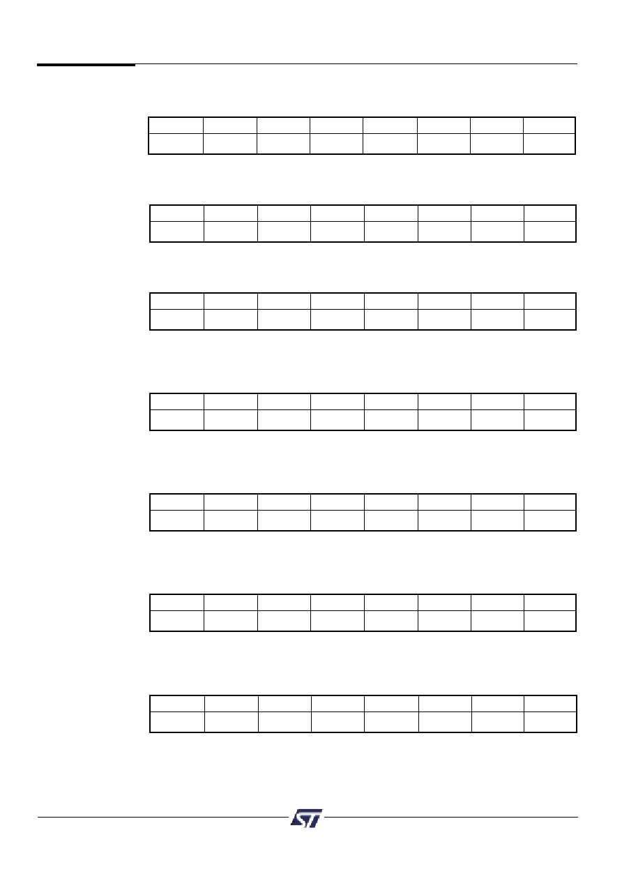
Bit 7
Bit 6
Bit 5
Bit 4
Bit 3
Bit 2
Bit 1
Bit 0
Port Pin 7
Port Pin 6
Port Pin 5
Port Pin 4
Port Pin 3
Port Pin 2
Port Pin 1
Port Pin 0
Data In Registers – Port A, B, C, D, E, F and G
8.0
Register Bit
Definition
All the registers in the PSD4000 are included here for reference. Detail description of the
registers are found in the Functional Block section of the Data Sheet.
Bit definitions:
Read only registers, read Port pin status when Port is in MCU I/O input Mode.
Bit 7
Bit 6
Bit 5
Bit 4
Bit 3
Bit 2
Bit 1
Bit 0
Port Pin 7
Port Pin 6
Port Pin 5
Port Pin 4
Port Pin 3
Port Pin 2
Port Pin 1
Port Pin 0
Data Out Registers – Port A, B, C, D, E, F and G
Bit definitions:
Latched data for output to Port pin when pin is configured in MCU I/O output mode.
Bit 7
Bit 6
Bit 5
Bit 4
Bit 3
Bit 2
Bit 1
Bit 0
Port Pin 7
Port Pin 6
Port Pin 5
Port Pin 4
Port Pin 3
Port Pin 2
Port Pin 1
Port Pin 0
Direction Registers – Port A, B, C, D, E, F and G
Bit definitions:
Set Register Bit to 0 = configure corresponding Port pin in Input mode (default).
Set Register Bit to 1 = configure corresponding Port pin in Output mode.
Bit 7
Bit 6
Bit 5
Bit 4
Bit 3
Bit 2
Bit 1
Bit 0
Port Pin 7
Port Pin 6
Port Pin 5
Port Pin 4
Port Pin 3
Port Pin 2
Port Pin 1
Port Pin 0
Control Registers – Ports E, F and G
Bit definitions:
Set Register Bit to 0 = configure corresponding Port pin in MCU I/O mode (default).
Set Register Bit to 1 = configure corresponding Port pin in Latched Address Out mode.
Bit 7
Bit 6
Bit 5
Bit 4
Bit 3
Bit 2
Bit 1
Bit 0
Port Pin 7
Port Pin 6
Port Pin 5
Port Pin 4
Port Pin 3
Port Pin 2
Port Pin 1
Port Pin 0
Drive Registers – Ports A, B, D, E, and G
Bit definitions:
Set Register Bit to 0 = configure corresponding Port pin in CMOS output driver (default).
Set Register Bit to 1 = configure corresponding Port pin in Open Drain output driver.
Bit 7
Bit 6
Bit 5
Bit 4
Bit 3
Bit 2
Bit 1
Bit 0
Port Pin 7
Port Pin 6
Port Pin 5
Port Pin 4
Port Pin 3
Port Pin 2
Port Pin 1
Port Pin 0
Drive Registers – Ports C and F
Bit definitions:
Set Register Bit to 0 = configure corresponding Port pin as CMOS output driver (default).
Set Register Bit to 1 = configure corresponding Port pin in Slew Rate mode.
Bit 7
Bit 6
Bit 5
Bit 4
Bit 3
Bit 2
Bit 1
Bit 0
Sec7_Prot
Sec6_Prot
Sec5_Prot
Sec4_Prot
Sec3_Prot
Sec2_Prot
Sec1_Prot Sec0_Prot
Flash Protection Register
Bit definitions: Read Only Register
Sec<i>_Prot
1 = Flash Sector <i> is write protected.
Sec<i>_Prot
0 = Flash Sector <i> is not write protected.
相關PDF資料 |
PDF描述 |
|---|---|
| PSD4235G2V-C-15B81 | Flash In-System-Programmable Peripherals for 16-Bit MCUs |
| PSD4825 | |
| PSD4850 | |
| PSD4890 | |
| PSD4810 | |
相關代理商/技術(shù)參數(shù) |
參數(shù)描述 |
|---|---|
| PSD4256G6V-10UI | 功能描述:CPLD - 復雜可編程邏輯器件 3.3V 8M 100ns RoHS:否 制造商:Lattice 系列: 存儲類型:EEPROM 大電池數(shù)量:128 最大工作頻率:333 MHz 延遲時間:2.7 ns 可編程輸入/輸出端數(shù)量:64 工作電源電壓:3.3 V 最大工作溫度:+ 90 C 最小工作溫度:0 C 封裝 / 箱體:TQFP-100 |
| PSD4-36 | 制造商:Tamura Corporation of America 功能描述: |
| PSD-45 | 制造商:MEANWELL 制造商全稱:Mean Well Enterprises Co., Ltd. 功能描述:45W DC-DC Single Output Switching Power Supply |
| PSD-45_11 | 制造商:MEANWELL 制造商全稱:Mean Well Enterprises Co., Ltd. 功能描述:45W DC-DC Single Output Switching Power Supply |
| PSD-45A-05 | 功能描述:線性和開關式電源 30W 5Vout 6A Input 9.2-18VDC RoHS:否 制造商:TDK-Lambda 產(chǎn)品:Switching Supplies 開放式框架/封閉式:Enclosed 輸出功率額定值:800 W 輸入電壓:85 VAC to 265 VAC 輸出端數(shù)量:1 輸出電壓(通道 1):20 V 輸出電流(通道 1):40 A 商用/醫(yī)用: 輸出電壓(通道 2): 輸出電流(通道 2): 安裝風格:Rack 長度: 寬度: 高度: |
發(fā)布緊急采購,3分鐘左右您將得到回復。