- 您現(xiàn)在的位置:買賣IC網(wǎng) > PDF目錄230919 > RDC-19222-202 (DATA DEVICE CORP) SYNCHRO OR RESOLVER TO DIGITAL CONVERTER, PQCC44 PDF資料下載
參數(shù)資料
| 型號: | RDC-19222-202 |
| 廠商: | DATA DEVICE CORP |
| 元件分類: | 位置變換器 |
| 英文描述: | SYNCHRO OR RESOLVER TO DIGITAL CONVERTER, PQCC44 |
| 封裝: | PLASTIC, LCC-44 |
| 文件頁數(shù): | 19/24頁 |
| 文件大小: | 1233K |
| 代理商: | RDC-19222-202 |
4
Data Device Corporation
www.ddc-web.com
RDC-19220 SERIES
V-12/08-0
THEORY OF OPERATION
The RDC-19220 Series of converters are single CMOS custom
monolithic chips. They are implemented using the latest IC tech-
nology which merges precision analog circuitry with digital logic
to form a complete, high-performance tracking Resolver-to-
Digital converter. For user flexibility and convenience, the con-
verter bandwidth, dynamics and velocity scaling are externally
set with passive components.
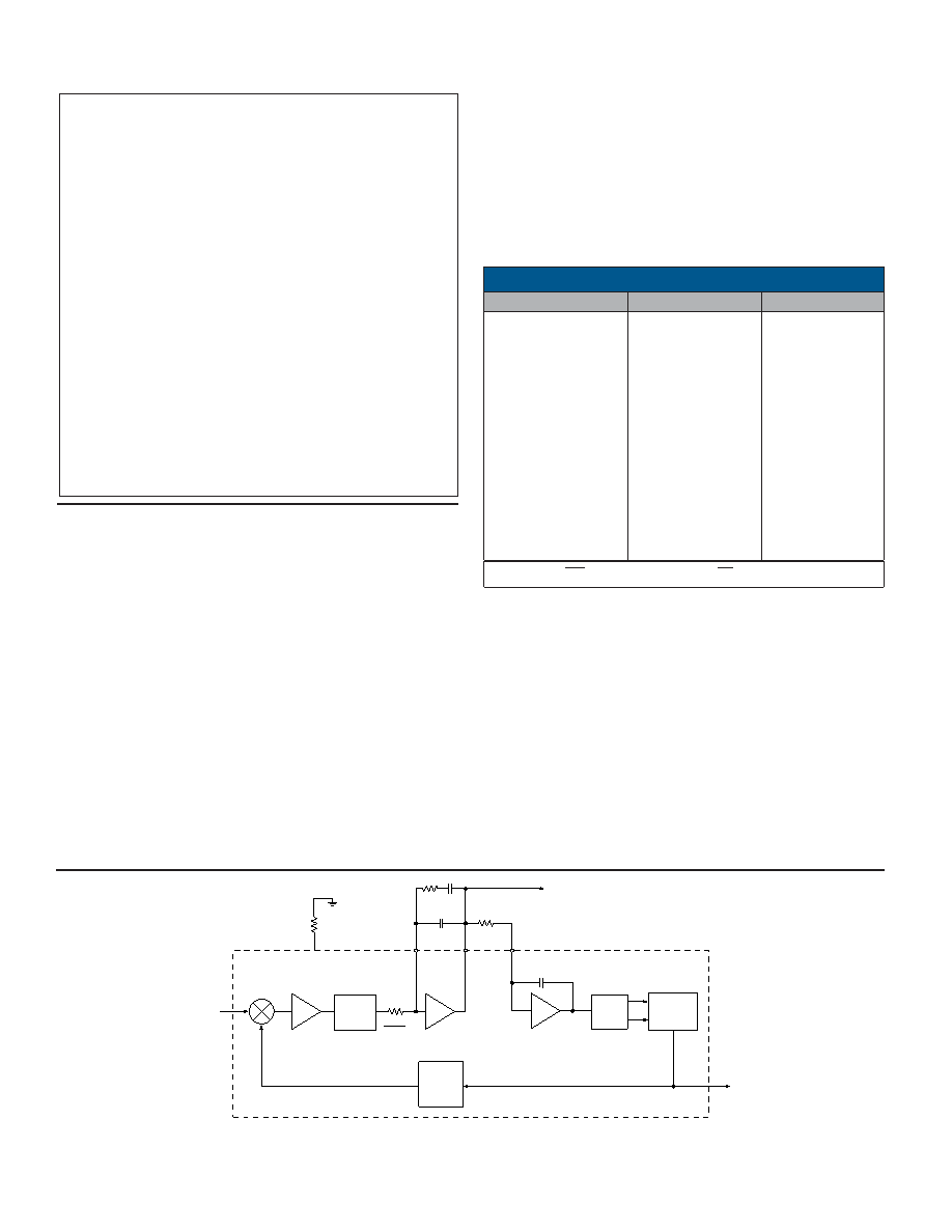
FIguRE 1 is the functional block diagram of the RDC-19220
Series. The converter operates with ±5 Vdc power supplies.
Analog signals are referenced to analog ground, which is at
ground potential. The converter is made up of two main sections;
a converter and a digital interface. The converter front-end con-
sists of sine and cosine differential input amplifiers. These inputs
are protected to ±25 V with 2 k resistors and diode clamps to
the ±5 Vdc supplies. These amplifiers feed the high accuracy
Control Transformer (CT). Its other input is the 16-bit digital angle
φ. Its output is an analog error angle, or difference angle,
between the two inputs. The CT performs the ratiometric trigono-
metric computation of SINθCOSφ - COSθSINφ = SIN(θ-φ) using
amplifiers, switches, logic and capacitors in precision ratios.
Note: The transfer function of the CT is normally trigonometric,
but in LDVT mode the transfer function is triangular (lin-
GAIN
11 mV/LSB
16 BIT
UP/DOWN
COUNTER
R1
VCO
RV
RB CBW
C
/10
BW
VEL
-VCO
H = 1
-VSUM
VEL
C F
S S
CT
+
-
RESOLVER
INPUT
(
θ)
RS
50 pf
CVCO
DIGITAL
OUTPUT
(
φ)
DEMOD
±1.25 V
THRESHOLD
1
FIGURE 2. TRANsFER FUNcTION BLOcK dIAGRAM #1
TABLE 2. dIGITAL ANGLE OUTPUTs
BIT
dEG/BIT
MIN/BIT
1(MSB)
2
3
4
5
6
7
8
9
10
11
12
13
14
15
16
180
90
45
22.5
11.25
5.625
2.813
1.405
0.7031
0.3516
0.1758
0.0879
0.0439
0.0220
0.0110
0.0055
10800
5400
2700
1350
675
337.5
168.75
84.38
42.19
21.09
10.55
5.27
2.64
1.32
0.66
0.33
Note: EM enables the MSBs and EL enables the LSBs.
ear) and could thereby convert any linear transducer out-
put.
The converter accuracy is limited by the precision of the comput-
ing elements in the CT. For enhanced accuracy, the CT in these
converters uses capacitors in precision ratios, instead of the
more conventional precision resistor ratios. Capacitors, used as
computing elements with op-amps, need to be sampled to elimi-
nate voltage drifting. Therefore, the circuits are sampled at a high
rate (67 kHz) to eliminate this drifting and at the same time to
cancel out the op-amp offsets.
The error processing is performed using the industry standard
technique for type II tracking R/D converters. The dc error is
Notes for TABLE 1:(from previous page)
1. unused data bits are set to logic “0.”
2. In LVDT mode, bit 16 is LSB for 14-bit resolution or bit 12 is LSB for
10-bit resolution.
3. Accuracy spec below for LVDT mode, null to + full scale travel (45
degrees).(2 wire-LVDT configuration).
4 Min part = 0.15% + 1 LSB of full scale “resolution set”.
2 Min part = 0.07% + 1 LSB of full scale “resolution set”
Accuracy spec below for LVDT mode, null to + full scale travel (90
degrees).(3 wire-LVDT configuration).
4 Min part = 0.07% + 1 LSB of full scale “resolution set”.
2 Min part = 0.035% + 1 LSB of full scale “resolution set”
Note that this is the converter spec only and does not consider the
front end external resistor tolerances.
4. See text, general Setup Considerations and HigherTracking Rates.
5. See text: general Setup Considerations for RDC19222.
6. Any unused input pins may be left floating (unconnected). All input
pins are internally pulled-up to +5 Volts.
7. Ka = Acceleration constant, for a full definition see the RD/RDC
application manual acceleration lag section.
8. When using internally generated -5V, the internal -5V charge pump
when measured at the converter pin, can read as low as -20% (or
-4V).
9. No 180° hangup with A/C reference.
10. When in overload condition the converter will not operate to speci-
fication and will not be damaged.
相關(guān)PDF資料 |
PDF描述 |
|---|---|
| RD-14591F1-232Q | SYNCHRO OR RESOLVER TO DIGITAL CONVERTER, CDMA36 |
| RDC-630-A-L-1-R | SYNCHRO OR RESOLVER TO DIGITAL CONVERTER, DMA27 |
| RD-14595F5-414 | SYNCHRO OR RESOLVER TO DIGITAL CONVERTER, CDFP36 |
| RD-14590F1-524L | SYNCHRO OR RESOLVER TO DIGITAL CONVERTER, CDMA36 |
| RD-14590F1-804L | SYNCHRO OR RESOLVER TO DIGITAL CONVERTER, CDMA36 |
相關(guān)代理商/技術(shù)參數(shù) |
參數(shù)描述 |
|---|---|
| RDC-19222-202T | 制造商:未知廠家 制造商全稱:未知廠家 功能描述:LVDT/Resolver-to-Digital Converter |
| RDC-19222-203 | 制造商:未知廠家 制造商全稱:未知廠家 功能描述:LVDT/Resolver-to-Digital Converter |
| RDC-19222-203T | 制造商:未知廠家 制造商全稱:未知廠家 功能描述:LVDT/Resolver-to-Digital Converter |
| RDC-19222-301 | 制造商:未知廠家 制造商全稱:未知廠家 功能描述:LVDT/Resolver-to-Digital Converter |
| RDC19222-301 | 制造商: 功能描述: 制造商:undefined 功能描述: |
發(fā)布緊急采購,3分鐘左右您將得到回復(fù)。